Continue to Site

Welcome to EDAboard.com

Welcome to our site! EDAboard.com is an international Electronics Discussion Forum focused on EDA software, circuits, schematics, books, theory, papers, asic, pld, 8051, DSP, Network, RF, Analog Design, PCB, Service Manuals... and a whole lot more! To participate you need to register. Registration is free. Click here to register now.

IF signal amplify without delay

Status
Not open for further replies.

himadri117

Newbie level 5
Joined
Sep 30, 2009
Messages
9
Helped
0
Reputation
0
Reaction score
0
Trophy points
1,281
Location
Kolkata
Activity points
1,377
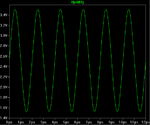
I have a RF Frontend that has an 4 IF signal output (2 I channel and 2 Q channel from 2 receiving anettans). Each channel of the IF has a signal rangining from 1.5V to 3.5V with a DC offset of 2.5V.

IF output signal:
2gx2zd1.png

I want to sample the signal with an ADC that has a reference voltage from 0 to 5V and use the mid range of 2.5V for better sampling.

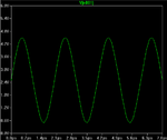
So,I prefer to shift the signal and amplify to make it from 0.5V to 4.5V with a offset of 2.5V.

Desired output signal
2cmvkt4.png

I tried coupled capacitor then level shift and gain with op-amp, also other shifting circuit, but the coupled capacitor to block the DC causes a little phase shift which is not desireable. So I don't want to filter the DC and aamplify to my desired signal. Please suggest me a circuit that will work without delay and phase shift.
 
Last edited by a moderator:

You will never, ever have zero phase shift*. You may set a
maximum, and then work to meet that goal. But a goal that
is physically unrealizable (like zero delay, zero power, zero
distortion, infinite bandwidth, infinite gain, infinite supply
rejection, zero noise figure and on and on) only delays you
getting down to realistic designing.

* 360 degrees is not the same as zero.
 

I don't understand the phase shift problem.

1. A first order high-pass used for level shifting has a phase shift of atan(fc/f), the value can be made arbitrarily small by implementing a respective low cut-off frequency.

2. A constant phase-shift that is equal for all channels doesn't matter at all.
 

input = "1.5V to 3.5V with a DC offset of 2.5V.", output = " it from 0.5V to 4.5V with a offset of 2.5V.". So you want a DC coupled opamp with a gain of 2 with an off set of -2.5V?
Frank

Thanks for the reply. I want a gain of 2 but the offset at 2.5V.
I tried using a coupled capacitor to first filter the Dc, then with voltage divider and opamp to shift the level and add some gain, but I"m not able to add considerable again to the circuit. Is my approach wrong, to filter the DC first?
 

If you AC couple, you loose the DC component in addition iif the signal is not perfectly symetrical, then it will "bounce" about as the charge on the capacitor changes to equalise the "equal area" above and below the output mean DC level. With video it is very importent to maintain the DC level right from the camera to the viewing device, so there are circuits called black level clamps to re-instate the correct DC level, which might be useful here. You could measure the positive peak and the negative peak then manipulate these figures in an opamp to give you the actual "zero" voltage of your signal then use this to offset the DC level of the opamp which has the gain of two.
Frank
 

Hi,

your signal frequency seems to be in the order of 500kHz.

You need a high speed OPAMP. Dc coupling intruduces no phase shift (except by the OPAMP itself).
AC coupling with capacitor allways intrudice a phase shift. But the larger the capacitor, the smaller the phase shift.
Use high quality capacitors. I recommend foil. If yoiu use ceramics, then COG/NP0, but they are low capacitance.

Good luck

Klaus
 

So here is a LT spice circuit I made to level shift after removing the DC offset.

Capture.PNG

The signal has very low amplitude now.Can you suggest a circuit to keep the DCoffset at 2.5V andamplify the signal from 0.5v to 4.5V?
 

Hi,


change R5 to 25k and connect the left side of R5 instead of GND to V2.
delete R1


Or even simpler:
delete C1, R1, R2, V2, R3
Connect V1 directely to + of OPAMP
change R5 to 25k
instead of connecting R5 directely to GND connect it with a series capacitor of 1u to GND

Klaus
 
Last edited:

Status
Not open for further replies.

Similar threads

Part and Inventory Search

Welcome to EDABoard.com

Sponsor

Back
Top