Continue to Site

Welcome to EDAboard.com

Welcome to our site! EDAboard.com is an international Electronics Discussion Forum focused on EDA software, circuits, schematics, books, theory, papers, asic, pld, 8051, DSP, Network, RF, Analog Design, PCB, Service Manuals... and a whole lot more! To participate you need to register. Registration is free. Click here to register now.

[PIC] If i didn't configure my header properly will it damage my microcontroller?

Status
Not open for further replies.

Sonu21091990

Newbie level 6
Joined
Dec 17, 2016
Messages
12
Helped
0
Reputation
0
Reaction score
0
Trophy points
1
Activity points
83

In the file that shows as 'header.txt', put a *single* call to <xc.h> before the pragma lines.
In the 'main.txt' file, you can get rid of the stdio and stdlib includes - if you REALLY want to have them (they are just a waste of space here) then they should go after the xc.h include.
I assume the 'newfile.h' include somehow includes the 'header.txt' file.
You don't need the 'jmp1' label nor the 'goto'. Simply replace the 'if(GP4==0)' with 'if(GP4)' or '(if(GP4==1)' and also get rid of the code that follows and keep the part after the 'else'.
Of course, once your code sees GP4 high, it will set the other outputs but they are never reset back to 0.
Once you have those things sorted, you need to tell us what you mean by the MCU becomes 'faulty'. WHat does it do that it should not? What does it not do that it should?
What programmer are you using?
Susan
 
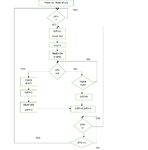
actually my program has several forward and backward jump. so i don't know how to do it without goto. please help me. here is the flow chart 12f629 flowchart.png
 

when i insert the hex file into microcontroller it became faulty

Is that code working on simulation environment ?
Did you check if programmer somehow changed configuration bits to other settings different from what you defined on code ?

Note: I can not see what you posted on the external forum sharing service.
 
You really should restructure your code so that it flows better. While it is possible to program that flowchart, it will result in code that is a total mess and very hard to write, document and maintain.
Forward 'jumps' can be handled by 'if' statements that conditionally provide access to the code that is 'jumped over'.
Backward 'jumps' can be handled with looping statements such as 'while' and 'for' (to use 'c' programming construct language).
There can be quite a steep learning curve toprogramming MCUs but once you have the first program working then a lot of the 'underlying mechanics' is the same for many other programs on the hardware. For example, to get a LED to flash (at all, better yet at the freqency you designed) you need to have the hardware connected correctly, the oscillator set up properly (and if you are using a crystal then the hardware around that must be correct), the power-on configuration options correct, the programmer/debugger hooked up and working and the IDE/compiler able to generate runnable files and program the device.
Finally, you need to make sure that the code files are correctly structured so that you can expand out form the 'flash a LED' code to the program that you actually want.
I suggest that you start
Susan
 
thanks everyone.I am very sorry for not replying. i have done this without using any goto statement. i have simulate it in proteas8. I have found that band gap value is changed in pickit 2. when i read the MCU it was 1000. After i programmed it i saw it changes to 0000. Please tell me how to set the band gap values. thanks again
 

here is my code


Code C - [expand]
1
2
3
4
5
6
7
8
9
10
11
12
13
14
15
16
17
18
19
20
21
22
23
24
25
26
27
28
29
30
31
32
33
34
35
36
37
38
39
40
41
42
43
44
45
46
47
48
49
50
51
52
53
54
55
56
57
58
59
60
61
62
63
64
65
66
67
68
69
* Author: user
 *
 * Created on 28 December, 2016, 10:55 AM
 */
 
#include <stdio.h>
#include <stdlib.h>
#include "new12f629.h"
 
int main(int argc, char** argv) 
{
    TRISIO=0b111000;
    CMCON=0b00000111;
    GPIObits.GP0=0;
    GPIObits.GP1=0;
    GPIObits.GP2=0;
    int k;
    //CLRWDT();
    while(1)
    {
        while(GP4==0)//checking input 2
        {
            GP0=1;//output 1 is on
            __delay_ms(10000);
            GP1=1;// output 2 on
            int count=0;//timers on for 2.5 mins
            while(count<31)
            {
                if(GP5==1)//checking input 2
                {
                    GP2=1;//output 3 on
                    count=0;
                    __delay_ms(40000);
                    break;
                }
                else
                {
                    count++;
                    __delay_ms(5000);
                    continue;
                }
            }
            GP0=0;
            GP1=0;
            GP2=0;
            k=0;
            while(k==0)
            {
                if(GP3==1)
                {
                    k++;
                }
                else if(GP3==0)
                {
                    if(GP4==1)
                    {
                        break;
                    }
                    else
                    {
                        k=0;
                    }
                }
            }
        }
    }
    
    return (EXIT_SUCCESS);
}

 
Last edited by a moderator:

Tell me what exactly do you want and I will write a code for you.
 
here is my code

You are not using any proprocessor directive to tell compiler to define the fuses in .hex file. This causes the programmer to use the default setting unless you manually change it immediately after loading the binary file into application buffer.
 
Tell me what exactly do you want and I will write a code for you.

thanks.i have uploded my flow chart.

- - - Updated - - -

You are not using any proprocessor directive to tell compiler to define the fuses in .hex file. This causes the programmer to use the default setting unless you manually change it immediately after loading the binary file into application buffer.

thanks again. please tell me how to do it
 

You are not using any proprocessor directive to tell compiler to define the fuses in .hex file. This causes the programmer to use the default setting unless you manually change it immediately after loading the binary file into application buffer.

thanks. i have defined my configuration bits in the header file. did i miss something?
 

Status
Not open for further replies.

Similar threads

Part and Inventory Search

Welcome to EDABoard.com

Sponsor

Back
Top