Continue to Site

Welcome to EDAboard.com

Welcome to our site! EDAboard.com is an international Electronics Discussion Forum focused on EDA software, circuits, schematics, books, theory, papers, asic, pld, 8051, DSP, Network, RF, Analog Design, PCB, Service Manuals... and a whole lot more! To participate you need to register. Registration is free. Click here to register now.

ICLl7107 4 DIGITS METER SHOWING LESS VALUE

Status
Not open for further replies.

mavi0249

Newbie level 4
Joined
Dec 11, 2015
Messages
5
Helped
0
Reputation
0
Reaction score
0
Trophy points
1
Activity points
34
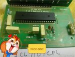
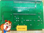
I m facing problem with voltage transducer using icl7107 it is using input pt voltage 110v /220kv. When i feed 110v ac it shows the value 27 v only but it hv to display 220v instead of 27v ac. Plz guide me . Secondly also variation of 4v in each reading.
 

Hi,

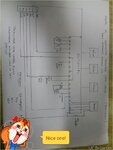
The cause could be one of many things, can you post a schematic of your circuit, please? It will help members to understand possible reasons. Thanks.
 

TMPDOODLE1450070859558.jpgTMPDOODLE1450070997432.jpgTMPDOODLE1450071122708.jpg

Please solve the problem.
 

Hi,

The problem is obviously the family of rodents on your circuit, they're even in the schematic.

I'm referring to the Microchip Technologies datasheet for the TC7106/TC7107 and the Intersil ICL7107CPL datasheet, and it looks like some of the pin numbers differ from the IC you are using. I'm confused, your schematic shows a pinout that differs from both the Microchip datasheet 2 diferent available pinning options and the Intersil ICL7107CPL datasheet pinout.

It's hard to read the component values and some of the pin numbers in the schematic you posted as the writing is small, and sideways.

From the schematic, you could try connecting Analog Common (pin 32) to In Lo/Vin- (pin 30) and see if that resolves the issue, or is that what pin 31 to 26 connection is supposed to be?

Might be worth checking the common-mode range you are trying to measure is within what is possible for the 7107.

Easy mistake to make: If you haven't already, check you haven't calibrated 200mV for 2V scale or vice versa.

I had a recent problem with a 71xx ADC that turned out to be the integrating (/named "AZ" on Microchip datasheet) capacitor (pin 29) which I had damaged during soldering, so I only got very low readings (like your 27V that should read 220) until I replaced it.

Not that it will matter, but the 0.1uF on what are usually pins 33 and 34 can happily be 1uF.

Anyway, more dicrepancies: Not sure why the input and the 1M resistor is on what is usually Vin-/In Lo, and Vin+/In Hi goes nowhere; and another is that pins 21 to 24 on your schematic usually go to the backplane/gnd pin and the 100's display segments. I have no idea who makes your IC, so maybe I'm wrong, but I'd check how the schematic was drawn and perhaps how the circuit is wired, in case there's been an upside-down and backwards and it's soldered all the wrong way round event - if not then a place to start looking is with common mode range issues.
 

I will send u complete schematic tomorrow
 

Also....how are you converting from 110VAC to the 200mVDC that the 7107 requires?
 

Status
Not open for further replies.

Similar threads

Part and Inventory Search

Welcome to EDABoard.com

Sponsor

Back
Top