Continue to Site

Welcome to EDAboard.com

Welcome to our site! EDAboard.com is an international Electronics Discussion Forum focused on EDA software, circuits, schematics, books, theory, papers, asic, pld, 8051, DSP, Network, RF, Analog Design, PCB, Service Manuals... and a whole lot more! To participate you need to register. Registration is free. Click here to register now.

I would like your help in choosing the cooler for my triacs

tyilgin

Junior Member level 2
Joined
Jul 9, 2010
Messages
23
Helped
0
Reputation
0
Reaction score
0
Trophy points
1,281
Activity points
1,504
Hi,

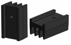
I have used triacs a few times in my work so far, and I have always used these triacs with the 57AS coolers shown in the picture in the TO220 case. The current flowing through it was never more than 5 amps.
I've never felt the need to monitor it in detail, but I've never noticed that the coolers got so hot that they became uncomfortable when touched.

Now I am thinking of using the triacs in the DPAK/D2PACK case, but I am doing research on whether the 1cm2 copper area I drew on the PCB will be sufficient for cooling.

Unfortunately, since I do not have the knowledge or equipment to evaluate the formulas I found as a result of my research, I could not understand them even though I found a few online calculation sites.

Could I please ask your opinions on whether 1cm2 copper area will be enough to cool my triac (Ex. BT137B-800G) under a 5A load?
 

Attachments

  • 57AS.png
    57AS.png
    118.2 KB · Views: 35
Hi,

I say: 1cm^2 is way too small.

First: consider all the surface area of the shown heatsink. It may add up to several 100 cm^2.

Then 1 cm^2 maybe is good for 0.5W, maybe 1W... but with 5A you get way more than 1W of power dissipation.

Also air flow will have big influence.

***
To calculate power disspation ... some things need to be considered.
Triacs have two mahor causes of power dissipation
1) the almost constant DC voltage in the range of 0.6 ... 1V typically
2) and the ohmic resistance of the conductive triac.

Sadly one needs two formulae for correct calculation.
1) [rectified_average_current] x triac_DC_voltage
2) [RMS_current] x [RMS_current] x triac_ohmic_resistance
To make it more difficult each current depends on waveform.

We simply don´t have enough information to do the calcualtions for you.

So my recommendation: stay with the previous solution and the big heatsink.

If this is not possible: use the previous setup and measure the temperature rise with your typical and worst_case situations.
(worst case: highest current, worst waveform, in a closed case, with low airflow...) --> then design your on_board heat spreader according the measured values.

Or: use the previous setup, but with a heatsink condition like in the heatsink datasheet. According temperature rise you may find out the power disspation.
--> then use an online tool to calculate the necessary on_board heat spreader.

Klaus
 
Yeah, hot to the touch means your airflow (and the surface area
exposed to it) are a significant portion of the "heat stack".

I have seen some intersting-looking heat sinks in tearing down
PCs and such, for component reclaim. Some seem to be trying
real hard to induce turbulence (which reduces airflow but helps
ensure that all the air contacts the sink at some point, not sliding
on through, laminar style). You could probably add ducting at low
actual cost, stuff like that; find better fan or add fan.

When you level up on power density you must expect the
"supporting actors" to make their own demands....
 

LaTeX Commands Quick-Menu:

Similar threads

Part and Inventory Search

Welcome to EDABoard.com

Sponsor

Back
Top