Continue to Site

Welcome to EDAboard.com

Welcome to our site! EDAboard.com is an international Electronics Discussion Forum focused on EDA software, circuits, schematics, books, theory, papers, asic, pld, 8051, DSP, Network, RF, Analog Design, PCB, Service Manuals... and a whole lot more! To participate you need to register. Registration is free. Click here to register now.

I need help with this project circuits

Status
Not open for further replies.

eng.mak88

Newbie level 4
Joined
Feb 11, 2013
Messages
5
Helped
0
Reputation
0
Reaction score
0
Trophy points
1,281
Activity points
1,315
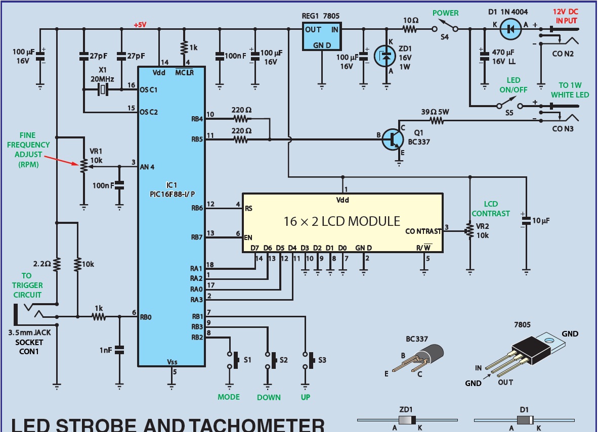
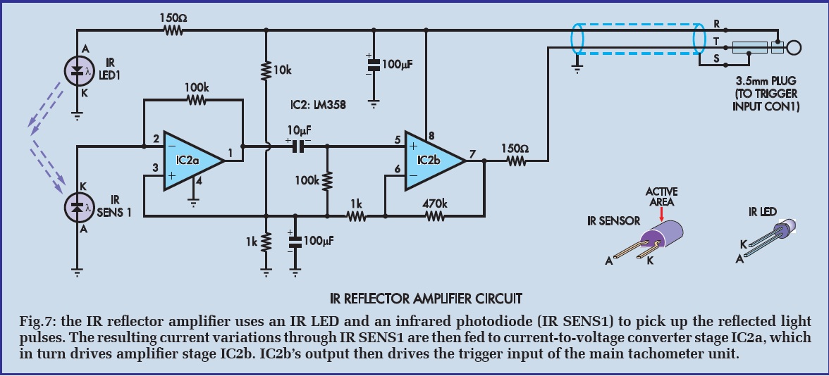
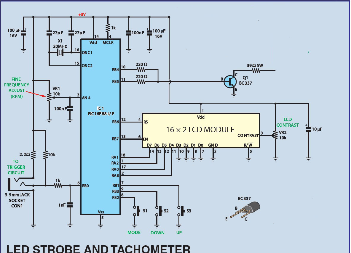
So I constructed this Tachometer project (it can measure RPM using 3 methods but I just chose one of them which is by IR LED and Photodiode) and I'm really sure that I did it right according to the circuits schematic I got from an electronics magazine, but when I connect the power supply its just dead and nothing works at all, please look at both circuits and tell me of there is anything wrong with it (I already found out that LCD pins 1 & 2 were connected wrong in this schematic)


Did you check the power supplies and the 20 MHz clock ? Did you also check if the pulses coming from the photodiod section are OK ? Are you sure the code of the PIC is correct ?
 

Did you check the power supplies and the 20 MHz clock ? Did you also check if the pulses coming from the photodiod section are OK ? Are you sure the code of the PIC is correct ?

yeah I used a 4-6v power supply, actually this pic shows how exactly I connected this circuit cause I didn't need the extra connection since I'm only using the IR circuit (CON1) (also I inverted the connection of LCD pins 1 & 2), so I just connect 4-6v but nothing works, and also here is the code I got also from the electronics magazine, do I HAVE TO connect the backlight pins of the LCD ?


Attachments

  • Tachometer Software.rar
    18.8 KB · Views: 102

Status
Not open for further replies.

Part and Inventory Search

Welcome to EDABoard.com

Sponsor

Back
Top