Continue to Site

Welcome to EDAboard.com

Welcome to our site! EDAboard.com is an international Electronics Discussion Forum focused on EDA software, circuits, schematics, books, theory, papers, asic, pld, 8051, DSP, Network, RF, Analog Design, PCB, Service Manuals... and a whole lot more! To participate you need to register. Registration is free. Click here to register now.

i need DC DC Converter(input 9-24V/ output 15V)

Status
Not open for further replies.

erenkcms

Junior Member level 3
Joined
Oct 31, 2006
Messages
25
Helped
2
Reputation
4
Reaction score
2
Trophy points
1,283
Location
Turkey
Activity points
1,448
Hi Everybody,
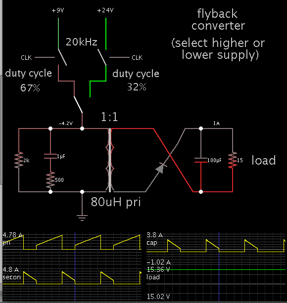
I need isolated dc/dc converter. Input is 9-24VDC output is 15VDC,1A. how can i design this. and what should the transformers specs be?
if you have this kind of schematics, could you share with me?(erenkcms@hotmail.com)
This is so urgent for me, if anybody can help me, i wil be pleasure..
thanks everybody.
 

Hi,

I'm not sure what you are looking for. There are ready to use devices.

If you want to design it your own, then look at the silicon manufacturer.
www.linear.com for example. There are a lot of application notes on how to do this.
Also there is a selection guide to find the right IC. Look for "flyback".

Hope this helps
Klaus
 

A flyback is able to do what you want.

I am experimenting with a simulation (just because I like to watch it running).
It shows you need a step-up transformer. Ratio 1:2.
For a 9V supply, use 56% duty cycle.
For a 24V supply, 28% duty cycle.
This should be able to provide 15V at 1A.

A primary with a Henry value of 50uH will allow you to run at frequencies in the area of 20kHz which is above the range of human hearing.


Thank you Bradtherad. which program ar you using, i like this.
by the way do you have any idea about transformer sizes? there are much more kind of trasnformers.
and if i want to create my fly back circuit with 1:2 transformer, what should i use primery side as snubber circuit (parallel to primary side of transformer)?
 

Hi,

For Transformer size , you can check this link :

This is a calculator for various Switching Topologies that calculates trans specification and suggest some cores with appropriate windings (with core code) (by Dr. Heinz Schmidt-Walter , Holger Wenzel, Thomas Zänker, Richard Morgan and Johnalan Kegan).

thank you memarian..
i have calculated that site for 9-24V in put and 1A/15V output, but i have some question about that.. for ex it gives me turns ratio as 1.05(N1(prim)/N2(seconder)...so when the input 9VDC, how can be 15VDC output? at max duty of primery,the output voltage will be 8.57VDC (N1/N2=V1/V2, 1.05=V1/V2, V2=V1/1.05=8.57VDC)..i can not understand this point..could you help me about this point? if you understand please explain me..
you can see calculated values from picture..
https://obrazki.elektroda.pl/4466928700_1398621539.jpg
 

Thank you Bradtherad. which program ar you using, i like this.

This is Falstad's animated interactive simulator. Free to download and use at:

www.falstad.com/circuit

by the way do you have any idea about transformer sizes? there are much more kind of trasnformers.

It must be sized to have 15W of power going through it. (Say 18W with losses.)

The wires must be a thick enough gauge to carry an average of 2 or 3A without overheating.
 

erenkcms, try to use program "PI expert" from Power Int. it design shem, calculate all components values and design transformer
 

thank you memarian..
i have calculated that site for 9-24V in put and 1A/15V output, but i have some question about that.. for ex it gives me turns ratio as 1.05(N1(prim)/N2(seconder)...so when the input 9VDC, how can be 15VDC output? at max duty of primery,the output voltage will be 8.57VDC (N1/N2=V1/V2, 1.05=V1/V2, V2=V1/1.05=8.57VDC)..i can not understand this point..could you help me about this point? if you understand please explain me..
you can see calculated values from picture..
https://obrazki.elektroda.pl/4466928700_1398621539.jpg

The calculator uses ideal components. It does not factor in any parasitic resistance. It assumes 100% efficiency.

My simulation added 1/2 ohm as a reasonable resistance. I found I was unable to get sufficient current flowing in the primary, within a duty cycle that allowed sufficient energy to go to the secondary. That is why I made the step-up ration 1:2, and reduced the Henry value below 100uH.

Seeing the results from the schmidt-walter calculator, I did more experiments with the simulation. As it turns out, a ratio of 1:1 is feasible. In fact this is more or less equivalent to a buckboost converter, with a single inductor.


Your supply specs can be achieved with more than one combination of component values. Your control circuit will adjust the frequency and duty cycle, depending on the supply V.

If you wind your own transformer, it is okay whether you add turns to the secondary for a 1:1, or 1:1.1, or 1:1.2, etc., ratio.
 
erenkcms, try to use program "PI expert" from Power Int. it design shem, calculate all components values and design transformer
is it free program?

- - - Updated - - -

The calculator uses ideal components. It does not factor in any parasitic resistance. It assumes 100% efficiency.

My simulation added 1/2 ohm as a reasonable resistance. I found I was unable to get sufficient current flowing in the primary, within a duty cycle that allowed sufficient energy to go to the secondary. That is why I made the step-up ration 1:2, and reduced the Henry value below 100uH.

Seeing the results from the schmidt-walter calculator, I did more experiments with the simulation. As it turns out, a ratio of 1:1 is feasible. In fact this is more or less equivalent to a buckboost converter, with a single inductor.


Your supply specs can be achieved with more than one combination of component values. Your control circuit will adjust the frequency and duty cycle, depending on the supply V.

If you wind your own transformer, it is okay whether you add turns to the secondary for a 1:1, or 1:1.1, or 1:1.2, etc., ratio.
thank you for you support.
 

thank you memarian..
i have calculated that site for 9-24V in put and 1A/15V output, but i have some question about that.. for ex it gives me turns ratio as 1.05(N1(prim)/N2(seconder)...so when the input 9VDC, how can be 15VDC output? at max duty of primery,the output voltage will be 8.57VDC (N1/N2=V1/V2, 1.05=V1/V2, V2=V1/1.05=8.57VDC)..i can not understand this point..could you help me about this point? if you understand please explain me..
you can see calculated values from picture..
http://obrazki.elektroda.pl/4466928700_1398621539.jpg

Hi,

When you hit the calculate Button, it will show the waveform in different points.

For Flyback SMPS Theory (and how it works) check this Link :
**broken link removed**
 

Status
Not open for further replies.

Similar threads

Part and Inventory Search

Welcome to EDABoard.com

Sponsor

Back
Top