Continue to Site

Welcome to EDAboard.com

Welcome to our site! EDAboard.com is an international Electronics Discussion Forum focused on EDA software, circuits, schematics, books, theory, papers, asic, pld, 8051, DSP, Network, RF, Analog Design, PCB, Service Manuals... and a whole lot more! To participate you need to register. Registration is free. Click here to register now.

how to use xilinx core generator in verilog code....

Status
Not open for further replies.
this is my code. i am using add and clock ip core. the output i am getting is 32 bit 0 stream. dont know what is problem, everything seems fine. i am getting two warnings at the of synthesize process and those are


WARNING:Xst:616 - Invalid property "SYN_BLACK_BOX 1": Did not attach to ad1.
WARNING:Xst:616 - Invalid property "SYN_NOPRUNE 1": Did not attach to ad1.


module pca(x,y,out,clk);

input [31:0] x,y;
input clk;
output [31:0] out;


addition ad1 (
.a(x), // input [31 : 0] a
.b(y), // input [31 : 0] b
.clk(CLK0_OUT), // input clk
.s(out) // output [31 : 0] s
);


clock clk1 (
.CLKIN_IN(clk),
.RST_IN(RST_IN),
.CLK0_OUT(CLK0_OUT),
.LOCKED_OUT(LOCKED_OUT)
);


now if anyone can help me sort it out. thank you
 

For a first time post about the same problem that is not the same, your code looks refreshingly reasonable! :)

I think what may be happening is that you forgot to declare the RST_IN signal. And verilog being verilog, this is one of the more annoying features where (if you use default settings) it will then conjure up a signal out of thin are, with default type wire. But it's not connected to anything, so all bets are off for that clock module...

So a couple of hints. 1) please use CODE tags or SYNTAX tags, this will generally make your code fragments more readible, and preserve any indentation you might have. 2) for general troubleshooting like this ... really really REALLY cultivate the habit to make testbenches for your code. I bet if you made a small testbench for this one (15 minutes work or so tops) then you'd see what is going on. Assuming this is the type of clock module from core generator which I think it is ... that means RST_IN is active high.

So either you declare RST_IN and give it some meaningful value for your design, or you do a quick test with this:

Code Verilog - [expand]
1
2
3
4
5
6
clock clk1 (
    .CLKIN_IN   (clk), 
    .RST_IN     (1'b0),     // no reset today since we're just testing...
    .CLK0_OUT   (CLK0_OUT), 
    .LOCKED_OUT (LOCKED_OUT)
);


(with some indentation thrown in for good measure, as example of improved readibility)


Anyways, hope that helps. If this doesn't fix it ... before you even post that is doesnt work: if no workey ==> make a testbench + post the testbench + screenshot. That is way faster than "help it doesn't work" back & forth 10 times. And if it does work ==> rejoice!
 

a.JPG

I tried what you said but it didn't work.
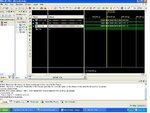
This is the test bench result. the output is still zero. i am posting the test bench screen shots and the simulation files. Hope it will be easier for you to help me out after seeing the code.
 

Attachments

  • test_4.rar
    1.2 MB · Views: 46

From test.v


Code Verilog - [expand]
1
2
3
4
5
6
7
8
9
10
11
12
13
14
15
16
17
18
19
20
21
22
23
24
25
26
27
28
29
30
31
module test;
 
    // Inputs
    reg [31:0] X;
    reg [31:0] Y;
    reg CLK;
 
    // Outputs
    wire [31:0] OUT;
 
    // Instantiate the Unit Under Test (UUT)
    pca uut (
        .X(X), 
        .Y(Y), 
        .OUT(OUT), 
        .CLK(CLK)
    );
 
    initial 
    begin
        // Initialize Inputs
    X = 45;
    Y = 23;
    CLK = 1;
        // Wait 100 ns for global reset to finish
    #100;
        
        // Add stimulus here
 
    end
endmodule


Well, looks like it is behaving as it should. Boring clock in, boring signals out... The hint was that in your screenshot you have CLK stuck HIGH. Your circuit isn't going to do much with a stuck clock.

You can add something like, right after where it says to Add stimulus here.

Code Verilog - [expand]
1
2
3
always begin
    #5 CLK <= ~CLK; // generate clock with period of 10 timeunits (presumably 10 ns) ... AKA 100 MHz clock
end


Status
Not open for further replies.

Part and Inventory Search

Welcome to EDABoard.com

Sponsor

Back
Top