Jordon
Member level 1
- Joined
- Dec 25, 2022
- Messages
- 33
- Helped
- 0
- Reputation
- 0
- Reaction score
- 0
- Trophy points
- 6
- Location
- Shanghai, China
- Activity points
- 262
Hi, I am trying to simulate a SRAM's function, which comes from MC2 software.
My original aim is to wrapper the SRAM to what I want, a sram with 1rw1r and related parameters are 32_256_8.
I mean, I want a commercial SRAM from MC2 to replace the open_sram(Open_SRAM_sky130).
So, I generate a dual port SRAM, and the final name is "xxxxxxxxx256x32m4mwa_130a_ssg0p9v125c.v".
The first problem comes, which file should me to do the test?
I mean there are DFT Verilog files(xxxxxxxx256x32m4mwa_130a_tmax.v) and normal Verilog files. And the files in DFT folder have a definition :
`define write_write forbidden,
consequently, I am not sure whether it is not appropriate for function simulation, I want to test the write and read function.
And, the second question comes followed: Why the SRAM doesn't work? I want to know how to debug, is there some specified means or options could help me find the where is the key?

I know it is not a problem which would fix easily, so I will provide more details as I can.
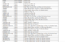
The SRAM only has the basic function with the command "./XXXX.pl -NonBIST -NonSLP -NonSD", so it has less interfaces, here is the list:
WTSEL, RTSEL, VG, VS,
AA, DA, BWEBA, WEBA, CEBA, CLKA,
BA, DB, BWEBB, WEBB, CEBB, CLKB,
AWT, QA, QB
And all the pins are attached some wires or value, no pins are floating.
I have set the related pins like the description in the datebook as follows.

Thanks a lot for your time.
My original aim is to wrapper the SRAM to what I want, a sram with 1rw1r and related parameters are 32_256_8.
I mean, I want a commercial SRAM from MC2 to replace the open_sram(Open_SRAM_sky130).
So, I generate a dual port SRAM, and the final name is "xxxxxxxxx256x32m4mwa_130a_ssg0p9v125c.v".
The first problem comes, which file should me to do the test?
I mean there are DFT Verilog files(xxxxxxxx256x32m4mwa_130a_tmax.v) and normal Verilog files. And the files in DFT folder have a definition :
`define write_write forbidden,
consequently, I am not sure whether it is not appropriate for function simulation, I want to test the write and read function.
And, the second question comes followed: Why the SRAM doesn't work? I want to know how to debug, is there some specified means or options could help me find the where is the key?
I know it is not a problem which would fix easily, so I will provide more details as I can.
The SRAM only has the basic function with the command "./XXXX.pl -NonBIST -NonSLP -NonSD", so it has less interfaces, here is the list:
WTSEL, RTSEL, VG, VS,
AA, DA, BWEBA, WEBA, CEBA, CLKA,
BA, DB, BWEBB, WEBB, CEBB, CLKB,
AWT, QA, QB
And all the pins are attached some wires or value, no pins are floating.
I have set the related pins like the description in the datebook as follows.
Thanks a lot for your time.
Attachments
Last edited: