Continue to Site

Welcome to EDAboard.com

Welcome to our site! EDAboard.com is an international Electronics Discussion Forum focused on EDA software, circuits, schematics, books, theory, papers, asic, pld, 8051, DSP, Network, RF, Analog Design, PCB, Service Manuals... and a whole lot more! To participate you need to register. Registration is free. Click here to register now.

How to see conversion of verilog design into boolean logic equations

Status
Not open for further replies.

tariq786

Advanced Member level 2
Joined
Feb 24, 2004
Messages
562
Helped
67
Reputation
134
Reaction score
53
Trophy points
1,308
Location
USA
Activity points
3,048
Hi Guys,

I have a question. Is there any way, i can view the boolean logic equations of my verilog design?

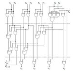
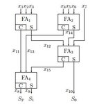
For example, if my design consists of full adders, decoders, muxes and basic logic gates, how can i see the boolean logic equations of all the outputs and intermediate nodes?

Any tools or design flow for this?
 

No one in 8 months?

Any tool, clue, pointer etc??

This brings back another question. How do synthesis tool work? Dont they need to do the above to minimize logic or eliminate redundant logic?

How about simulators? Dont they need to do something similar?

Dave59 or anyone else could you answer this question?
 

hi tariq,
1. you need to compile your code (at least) by a compiler HDL tool. --> you will see logic and function, perhaps such as : symbol of adder, symbol of mux,....
2. you need to synthesis your code by a synthesizer tool. --> you will see logic level with what you "translate" from design to cells library.
 
Hoanglongroyal

Could you tell what compiler hdl tool will allow me to see logic and function as adder and muxes
 

No one in 8 months?
You mean, you haven't been able to find the answer within 8 months by yourself? :-(

All synthesis tools have an option to output gate level netlists for post-synthesis simulation. They refer to phsyical logic elements of the target hardware, but often contain a description of implemented equations. See below an example from a *.vho file generated by Altera Quartus for Mpdelsim gate level simulation.
Code:
\Add0~2\ : cycloneiii_lcell_comb
-- Equation(s):
-- \Add0~2_combout\ = \a[1]~input_o\ & (\b[1]~input_o\ & \Add0~1\ & VCC # !\b[1]~input_o\ & !\Add0~1\) # !\a[1]~input_o\ & (\b[1]~input_o\ & !\Add0~1\ # !\b[1]~input_o\ & (\Add0~1\ # GND))
-- \Add0~3\ = CARRY(\a[1]~input_o\ & !\b[1]~input_o\ & !\Add0~1\ # !\a[1]~input_o\ & (!\Add0~1\ # !\b[1]~input_o\))

-- pragma translate_off
GENERIC MAP (
	lut_mask => "1001011000010111",
	sum_lutc_input => "cin")
-- pragma translate_on
PORT MAP (
	dataa => \a[1]~input_o\,
	datab => \b[1]~input_o\,
	datad => VCC,
	cin => \Add0~1\,
	combout => \Add0~2_combout\,
	cout => \Add0~3\);
 
Tariq,

You need to give an example of what you are looking to see. Do you want to see a graphical schematic diagram in terms of logic gates? or are you looking for a text list of logic equations?
 
Hi Dave,
Thanks for your response. I am actually looking for both but i prefer a text list of logic equations. For example, here are two circuits for which i want the equations at the intermediate nodes and at the outputs

the first circuit is 4 bit parallel prefix adder in terms of and, or, xor gates.

the second is a one-counter (not the sequential counter) but a counter that counts the number of ones in 7 bits. It is based on full adders (FA) with 3 inputs and two outputs (carryout and sum)

Based on these two examples, how can i get logic equations of all the nodes in the circuit.

Thanks and please let me know if there are any further questions
 

Attachments

  • 4bit_ppadder.jpg
    4bit_ppadder.jpg
    14.6 KB · Views: 132
  • 3bit_counter.jpg
    3bit_counter.jpg
    10.5 KB · Views: 133

In Synopsys DesignCompiler:

1) read the RTL code
analyze <rtl_files>
elaborate
or read_verilog ...

2) convert RTL into logic equations in assign statements
compile -no_map

3) write out verilog files
write -f verilog -output <filename>
 
Oratie dude thanks very much.

I am waiting to hear from Dave59 as well. He might shed light from a different angle
 

Status
Not open for further replies.

Part and Inventory Search

Welcome to EDABoard.com

Sponsor

Back
Top