Continue to Site

Welcome to EDAboard.com

Welcome to our site! EDAboard.com is an international Electronics Discussion Forum focused on EDA software, circuits, schematics, books, theory, papers, asic, pld, 8051, DSP, Network, RF, Analog Design, PCB, Service Manuals... and a whole lot more! To participate you need to register. Registration is free. Click here to register now.

How to minimize the number of ESD diode protection?

Status
Not open for further replies.

michcfr

Advanced Member level 4
Joined
Mar 7, 2012
Messages
106
Helped
0
Reputation
0
Reaction score
0
Trophy points
1,296
Activity points
2,011
Hello,
I want to minimize the number of ESD diode protection to place on my circuit.

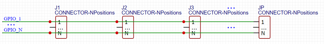
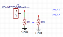
The circuit is a kind of bus of N GPIO lines shared by P connectors each with N pins (one per GPIO). See the figure 1. At the level of each connector, I would then place N ESD diodes (like in figure 2). So, the number of ESD diodes to place on my circuit is: PxN

But, I have P=8 connectors and N=36 GPIO lines, so I would need to place 288 ESD diodes!! this is huge, even with multiple channel ESD diodes ICs.

Now, I am looking for alternative solutions to minimize or fatorize the ESD diodes on my circuit. If somebody can help. Thank you


Regards,
Michel
 

Attachments

  • figure 1.png
    figure 1.png
    11.9 KB · Views: 132
  • figure 2.png
    figure 2.png
    12.5 KB · Views: 125

If you've got 288 lines, you're going to need 288 diodes to protect them. You can't change math. You might be able to minimize the number by identifying lines that don't need protection.
 

Hi,

I agree you can't reduce the count.

And since we don't have any idea about voltage, current, frequency, leakage current.... we are not able to recommend any devices.

I usually use double diodes, one to GND, the other to VCC. Like already written, there are devices that can protect multiple lines.

Klaus
 

thank you barry. I was expecting this kind of response :-(
GPIO are of classical protocols: I2C, I2S, UART, SPI but also ADC, PWM and classical GPIO (LOW/HIGH)
Does it helps?
--- Updated ---

Hi,

I agree you can't reduce the count.

And since we don't have any idea about voltage, current, frequency, leakage current.... we are not able to recommend any devices.

I usually use double diodes, one to GND, the other to VCC. Like already written, there are devices that can protect multiple lines.

Klaus
thank you Klaus for your response.
What are the advantages of double diodes, one to GND, the other to VCC against the one only connected to GND?

Michel
 
Last edited:

Presumably these are transzorb / zener type clamps?

If you had a double sided components board then the
right form factor clamp might fit nicely about the pins
of each connector and waste not much area.

The question of what's attached to these lines, and
whether those devices contain their own ESD clamps
deserves more consideration.
 

If signal is not so high frequency,normal capacitor is enough 0402 package. If with high frequency signal you can also try multi diode in one package
 

Hi,
What are the advantages of double diodes, one to GND, the other to VCC against the one only connected to GND?
Sorry for late reply.
Advantage .. or not...
It depends on the port you want to protect.

Example:
1)
See 74HC00 datasheet: https://assets.nexperia.com/documents/data-sheet/74HC_HCT00.pdf
It defines the "max input clamp current" for V_IN= -0.5V ... VCC+0.5V
It is related to VCC.
If VCC= 3.3V you should not apply mor ethan 3.8V.
If power down: VCC=0V, then you should not apply more than 0.5V
--> Thus I use a schottky diode to VCC

2)
See 74AHC00 datasheet: https://assets.nexperia.com/documents/data-sheet/74AHC_AHCT00.pdf
It defines the "max input voltage" -0.5V ... 7.0V
It is not related to VCC.
If VCC= 3.3V you may apply up to 7.0V. (5V input tolerant)
If power down: VCC=0V, then you still may apply up to 7.0V.
--> Thus I use a zener/TVS... or a schottky diode to VCC

Other advantages: fast, low threshold voltage, low capacitance

Conclusion:
With the schottky to VCC and a schottky to GND you are on the safe side.

Disadvantage of the schottky to GND:
There are circuits where a schottky to VCC is counter productive.
An example is: multiple RS485/RS422 devices on the same bus.
RS485 transceiver behave "neutral" = "high impedance" when not powered. Thus it´s possible to have some devices not powered up but still communication with other bus partners will work.
But if you use schottky diode to VCC on an unpowered RS485/RS422 bus, then it pulls down communication signals and the communication to all bus partners will fail.

Klaus
 

Status
Not open for further replies.

Part and Inventory Search

Welcome to EDABoard.com

Sponsor

Back
Top