markbng
Junior Member level 1
Hello,
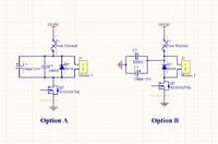
I am wondering how to make a good PWM controlled heater output. I am using a N FET that is controlled by a push-pull configuration (12V/0V) and the N FET has a 100 Ohm resistor connected to the gate. The PWM is a CTOUT output from the State Configurable Timer of the LPC controller (PWM output is connected to external push pull). I am only the hardware design engineer, so I don't know what frequency the software engineer will use for the PWM (recommendations?). I have 2 options for the PWM output. Option A has capacitors over the load. The load will get a DC voltage and there will not be many EMI problems, because the capacitors will buffer the output voltage. But I am concerned about the capacitors. For a high frequency a capacitor is a conductor (low capacitive reactance). Will the capacitors not cause much power loss? Is Option B a better way to get as much power as possible to the heater. Will this option not introduce much EMI (cables are approx. 1m long). The heater exists of a resistance/heating wire.
I also want to use a similar output configuration for controlling a 12VDC PC fan. What is the best output configuration?
Thanks in advance for your help.
Kind regards,
Mark
