Continue to Site

Welcome to EDAboard.com

Welcome to our site! EDAboard.com is an international Electronics Discussion Forum focused on EDA software, circuits, schematics, books, theory, papers, asic, pld, 8051, DSP, Network, RF, Analog Design, PCB, Service Manuals... and a whole lot more! To participate you need to register. Registration is free. Click here to register now.

How to make 1:1 connectors at home?

Status
Not open for further replies.

hotshot05

Junior Member level 2
Joined
Jun 4, 2011
Messages
21
Helped
0
Reputation
0
Reaction score
0
Trophy points
1,281
Activity points
1,469
IS it possible to make 1:1 connectors like these at home? Does anybody have any video links or other tutorials?

Link -1 to 1 Black Connector - Nex Robotics

And is it possible to make 1:1 male jumper wires instead of female?
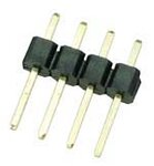
 

You can use male and female headers
HEADS.jpg FHEADS.jpg

The make headers can be cut one by one but in order to cut a single female pin it is better to remove the next pin (pull it from the back) and then cut a single female in the removed pin position.
All you need then is to solder a wire.

Alex
 

If, by making such items "at home", you mean making everything including the plastic bits, it's not very practicable. I second Alex's suggestion to make them out of readymade headers. I'd just like to add that there are also breakaway female connectors just like the male ones. This type is different from the one shown by Alex in that, like the male ones, there are notches in between adjacent pins and you can break off individual pins without sacrificing one pin to make cutting space.

And is it possible to make 1:1 male jumper wires instead of female?
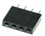
Of course. Just use the female pins on the PCB side.
 

I haven't seen any breakable female headers so I suppose they are harder to find.

I usually buy 40pin female (single or double ) headers and break them to any count of pins I need because buying a 5pin or 6pin header is more expensive

fheader2.gif

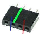
I always cut like the blue line which means that one pin at the cut point is destroyed (the green pin) because it is very hard to cut at exactly the middle like the red line and keep both pins at the sided intact.
I use a utility knife or a small saw or a dremel with cutting disk (thin metal saw disk).

Alex
 

Yes, female breakaways are less common than male ones, but they do exist. I may still have a few that I bought OTC on one of my past visits to a larger city (I live in a remote region). They look similar to this offering at Digikey -
**broken link removed**
 

Yes I have pins like these, I have seen them called machined pins just like the IC sockets

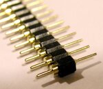
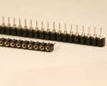
machined male pins.JPG machined female pins.JPG

The square male pin of the previous post can't fit in these females, these are round and thinner.
I usually use these when I make SMD to DIP adapters because they can be plugged in a IC socket.

Alex
 

You can use male and female headers
View attachment 65591 View attachment 65592

The make headers can be cut one by one but in order to cut a single female pin it is better to remove the next pin (pull it from the back) and then cut a single female in the removed pin position.
All you need then is to solder a wire.

Alex

I know this. But soldering wires to the end is the main problem. Is soldering possible in such small exposed area? And will the soldering be strong enough not to break every time I plug in the jack?
 

It depends on your soldering skills. It's no problem for someone with good soldering experience. If you keep plugging and unplugging it regularly, it may eventually break like everything else. But if the soldering is done properly, it will last a long time and the break is likely to be at the point where the bare wire joins the sleeving, not at the solder point.

It will last even longer if you cover the joint, including 5-10mm of unstripped wire, with heatshrink sleeving.
 

Status
Not open for further replies.

Similar threads

Part and Inventory Search

Welcome to EDABoard.com

Sponsor

Back
Top