Continue to Site

Welcome to EDAboard.com

Welcome to our site! EDAboard.com is an international Electronics Discussion Forum focused on EDA software, circuits, schematics, books, theory, papers, asic, pld, 8051, DSP, Network, RF, Analog Design, PCB, Service Manuals... and a whole lot more! To participate you need to register. Registration is free. Click here to register now.

how to interface 5V LCD with 3.3V MCU

Status
Not open for further replies.

prakashvenugopal

Advanced Member level 1
Joined
Jun 1, 2011
Messages
473
Helped
15
Reputation
30
Reaction score
15
Trophy points
1,298
Activity points
4,973
Dear sir,

I had interfaced 5V LCD with 5V MCU. But now i have to interface 5V LCD with 3.3V MCU. MCU will tolerant upto 3.3V. I have to read the data from LCD. Will it damage the MCU?
If yes, what to do to interface 5V LCD with 3.3V MCU ?

Regards,
V. Prakash
 

This question is also important for me.
i think use pull down resistances on data pins.

---------- Post added at 11:59 ---------- Previous post was at 11:57 ----------

LCD data pins are input only in write mode so dont worry

---------- Post added at 11:59 ---------- Previous post was at 11:59 ----------

but what about in read from lcd mode?
 

pulling down resistor on data pin? How? when we read from LCD, it will have 5V on that data lines due to LCD 5V VCC?
 

oh man why u r not connecting ur lcd with 3.3 volt rail
HD44780 datasheet page 48 topic DC characteristic
see the last line
 
Last edited:

hi,

I am using the LCD LM16200. refer the datasheet attached. It has 5V Vcc.
 

Attachments

  • LM16200.pdf
    32.1 KB · Views: 165

if u need to write data on lcd than it is not problem. but if u want to read also than i think pull down resistance could work . Another solution that i like and is proper to use 5v to 3v logic shift level as
74LCX245
Datasheet
https://www.fairchildsemi.com/ds/74/74LCX245.pdf


the above circuit is all you need to READ AND WRITE, the gate is connected to the low voltage source , R1 and R2 work as a pullups.

when L1 becomes low the mosfet turns on and H1 becomes low too,
in the reverse direction if H1 gets grounded then L1 will become low too because of the mosfet diode

Alex

Is this available in single tube package?

---------- Post added at 13:14 ---------- Previous post was at 13:14 ----------

as the TTL draw much current i mean 74 series TTL
 

Wait a second. If i got it correctly from that datasheet no level shifting is needed. It states that input voltages is read as low from -0.3 to 0.6 V and as high from 2.2V to VCC (which is 5V for lcd). Output voltage is 2.4V for high and below 0.4 for low.

I guess that based on those informations you could try to interface MCU directly to the lcd. I just don't know if the output high voltage is exactly 2.4, or from 2.4 up to VCC. If that's the case u might need some resistor + 3V1 zener. On the other hand many 3.3V MCUs have 5V tolerant inputs. Maybe u can get one of that kind?
 

hi,

Thanks for the replies. I had already designed my board. Adding a mosfet will not be possible in that board. For the next development i will go for the mosfet pr level shifter. Now i can use the 3.3V Zener diode in the data lines (D0 to D7)?Please let me know.

Regards,
V. Prakash
 

Try it?
It will not damadge your lcd or microcontroller as the voltages are 3.3v. So only one thing will be happened. That is
Working OR Fail
Try it and share it here for others
 

I have used LCD16x2 with dsPIC33 without any voltage buffer.
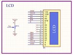
You can use 5VDC for LCD power, and 3.3V for MCU power. Data I/O can connect directly as the picture below.
1.JPG
2.JPG
 

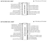
Note in page 6 of the datasheet https://ww1.microchip.com/downloads/en/DeviceDoc/70265E.pdf
that only a few of the mcu pins are 5v tolerant

dsPIC33.jpeg

In your schematic
RS, R/W and E are connected to 5v tolerant pins but DB4,5,6,7 are not so if you try to read data from the LCD you will have problems

Alex
 
If you connect all pins of LCD Control and LCD Data to 5V tolerant pin, your design will be better. But I have tested and finished my design with schematic in pre. post. It's running well up to now (2 months)
 

Zener draws unnecessary current. As suggested earlier SN74LVC4245A works best.
 

Status
Not open for further replies.

Similar threads

Part and Inventory Search

Welcome to EDABoard.com

Sponsor

Back
Top