Ali Z
Newbie level 6
Hi
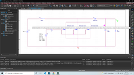
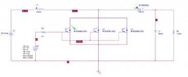
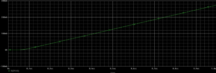
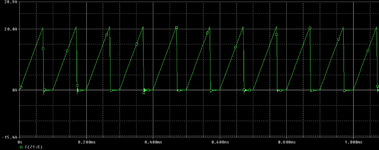
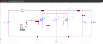
I am studying a dc dc converter model. My friend drew this circuit and got this graphic.
I added his circuit and graph . But I draw same model , same numbers for resistors capacitors v pulse source ,inductor, diode but my graph is very different.
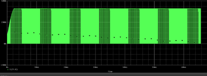
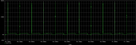
Actually my V pulse source looks like doesn't working . I added my Pspice design and graph . What is my mistake ?
Could you please help me ?
I am studying a dc dc converter model. My friend drew this circuit and got this graphic.
I added his circuit and graph . But I draw same model , same numbers for resistors capacitors v pulse source ,inductor, diode but my graph is very different.
Actually my V pulse source looks like doesn't working . I added my Pspice design and graph . What is my mistake ?
Could you please help me ?
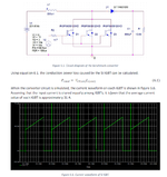

 ). I'm using LTspice very frequently, so I implemented your boost converter in LTspice. See the pictures below. There are no IGBTs available in LTspice, so I imported the provided SPICE model by Infineaon and created the symbol (I haven't but much effort in it).