Continue to Site

Welcome to EDAboard.com

Welcome to our site! EDAboard.com is an international Electronics Discussion Forum focused on EDA software, circuits, schematics, books, theory, papers, asic, pld, 8051, DSP, Network, RF, Analog Design, PCB, Service Manuals... and a whole lot more! To participate you need to register. Registration is free. Click here to register now.

How to dump program in msp430fg4618?

Status
Not open for further replies.
Its helpful sir.

program all MSP430Fxxx flash microcontrollers (note: parallel port JTAG doesn't support Spy-Bi-Wire devices as timing from parallel port can't meet programming specs)
uses TI standard 2x7 pin JTAG connector

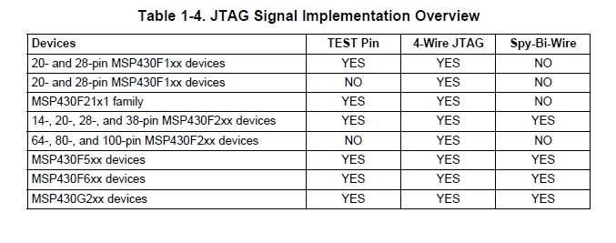
How to determine whether my device is SBW supported device?
 

The appropriate datasheet for the device will specify 4-wire, 2-wire (SBW) or both for the device's programming requirements.

MSP430F449 Product Page

MSP430x43x1, MSP430x43x, MSP430x44x1, MSP430x44x MIXED SIGNAL MICROCONTROLLER Datasheet

The signal labels for 4-wire JTAG are TDO, TDI, TMS, TCK and the signal labels for 2-wire Spy-Bi-Wire (SBW) JTAG are SBWTDIO and SBWTCK. A view of the devices pinout will show one or the other interface, possibly both.

Also the following has detailed programming specifications for each MSP430 variant:

**broken link removed**


BigDog
 
  • Like
Reactions: AnuHV

    AnuHV

    Points: 2
    Helpful Answer Positive Rating
Hello!

Both are in fact JTAG, 4-Wire and 2-Wire otherwise known as Spy-Bi-Wire (SBW)...

Yes of course, that can be done. However, you need to interface the launchpad and the F4X board.
I agree that for a student it can be a cheaper solution.

I made one project with the launhpad as a programmer (the board is a tiny 5529 board, and I wanted
to save space for the JTAG connector. Using the launchpad as a programmer is an endless source of
trouble. First it's awfully slow, loading a program really takes time. And on top of that it keeps loosing
the target and the fastest way to be back on track is to stop the IDE (I use IAR), unplug and replug
the launchpad and restart the IDE. When you do that 100 times a day, you loose 2 hours and gain
a fair level of nervous stress.

Fortunately for this project, as it was my first SBW experience, I had set a few test pins as a B-plan
in order to solder a regular JTAG extension, and I did it on the second day. Well, it's only my experience,
and it was only one experience, so I cannot definitely say it's a source of problems in any environment.
Maybe I have set something wrong on that board, but at least the regular JTAG works fine.

By the way, there is also an issue about the parallel port interface. I don't remember exactly what
because I don't use it, but I think it does not work on windows 7 or it does not work with the latest
IAR, anyway there is something about compatibility.

Dora.
 
  • Like
Reactions: AnuHV

    AnuHV

    Points: 2
    Helpful Answer Positive Rating
Sir,
i have found that the processor(MSP430F449) i am using is a 4-wire device since it has the following pins (TDO, TDI, TMS, TCK) as you said. I have bought this processor from olimex as a Header board.
Msp430-jtag tiny is the programmer that i am using.

the header board is connected with the programmer through 4 wire jtag and from the programmer it is connected to the pc using USB.


when i tried to debug and download a code into my kit following error is coming.
communication error:
check if hardware is connected
check if debug protocol (SBW or 4-wire) is correct

In IAR workbench kickstart version IDE that i am using there was a an option to change the protocol but it is set default as SBW .Manuall change option is highlighted for MSP430F449 alone.

could you please suggest something to clear this error?
 

In IAR workbench kickstart version IDE that i am using there was a an option to change the protocol but it is set default as SBW .Manuall change option is highlighted for MSP430F449 alone.

could you please suggest something to clear this error?

I do not have the Kickstart version of IAR, but the Full IAR EW for MSP430 version.

Have you checked the correct driver is selected in the IDE:

Project => Options =>Debugger, Drop Down Menu: Driver

Also:

Project => Options => Debugger => FET Debugger, Drop Down Menu: Connection => Olimex USB, Automatic

I have my protocol for the FET Debugger set as Automatic

Also make sure you have any required drivers loaded from Olimex.

BigDog

---------- Post added at 21:41 ---------- Previous post was at 21:16 ----------

I also found this step by step guide:

**broken link removed**

BigDog
 
  • Like
Reactions: AnuHV

    AnuHV

    Points: 2
    Helpful Answer Positive Rating
Hi sir,
I have ordered " MSP430 JTAG tiny" from olimex but they have delivered me "MSP430 JTAG TINY V2". Is there any difference between these two? will the driver software for these to differs?
Olimex has given few driver software for MSP430 JTAG TINY alone .i have installed it and when i checked the properties in device manager an error stating that " your device is not ready to start(code 10)" is coming.could you please tell some solution for it ?
 

Hi sir,
Now my programmer is working properly. The problem is because i dint use an apt device driver software.
 

I'm glad you managed to figure it out.

Good luck with your project. Post any further issues you may encounter.

BigDog
 
  • Like
Reactions: AnuHV

    AnuHV

    Points: 2
    Helpful Answer Positive Rating
hi sir,
Now getting an error after giving debug-->go like this
The stack pointer for stack 'Stack' (currently Memory:0xDDFE) is outside the stack range (Memory:0x9B0 to Memory:0xA00)


why this error is coming and what to do to eliminate this?
 

The error could be due to several issues.

Can you zip up your project directory and upload it?

Or post your code using the Code Tags?

BigDog
 

Hi sir,
first i tried this program
Code:
#include "io430.h"
void delay(int a);
void main(void)
{
  WDTCTL = WDTPW + WDTHOLD; // Stop watchdog timer
P1DIR |= 0xFF; 
for (;;)
{
    P1OUT = ~P1OUT ;
  delay(10);
 }
}

void delay(int a)
{
  volatile unsigned int i; // volatile to prevent optimization
 i = a*100; // SW Delay
   do i--;
    while (i != 0);
    
}
This is a simple program for blinking four led...
First the output came properly...but later when i tried the following counter program
Code:
#include "io430.h"
 void DELAY ();  
int main( void )
{
  // Stop watchdog timer to prevent time out reset
  WDTCTL = WDTPW + WDTHOLD;
  P1SEL=0X00;
  P1DIR=0XFF;
  P1OUT=0XFF;
 
for(;;)
{
P1OUT=0X0F;
DELAY(500);
P1OUT=0X0E;
DELAY(500);
P1OUT=0X0D;
DELAY(500);
P1OUT=0X0C;
DELAY(500);
P1OUT=0X0B;
DELAY(500);
P1OUT=0X0A;
DELAY(500);
P1OUT=0X09;
DELAY(500);
P1OUT=0X08;
DELAY(500);
P1OUT=0X07;
DELAY(500);
P1OUT=0X06;
DELAY(500);
P1OUT=0X05;
DELAY(500);
P1OUT=0X04;
DELAY(500);
P1OUT=0X03;
DELAY(500);
P1OUT=0X02;
DELAY(500);
P1OUT=0X01;
DELAY(500);
P1OUT=0X00;
DELAY(500);
}
  //return 0;
}
void DELAY (unsigned int d )
              {
               for(int k=0;k<d;k++)
               for(int j=0;j<786;j++);
              }
only three leds worked properly like a counter another one led was blinking as per the previous blinking program...

so i changed the led to port 6...
It was then i got the error as
The stack pointer for stack 'Stack' (currently Memory:0xDDFE) is outside the stack range (Memory:0x9B0 to Memory:0xA00)
 
Last edited:

iar1.png
This is the error yhat i am getting in IAR


WHEN I GAVE PROJECT-->DEBUG WITHOUT DOWNLOADING I AM GETTING AN ERROR AS

User error: Illegal opcode found on address 0x0
 
Last edited:

Hello!

1. The code in the picture cannot work because you initialize port 6 for output but you
try to toggle port 1. If it works, it means that port 1 was still set to output, but as far
as I remember, the default state at start up is 0. (Look at the docs for the default).

2. Your delay function may give you bad surprises.
I agree that if your clock is around 1MHz, which is the default in most of MSP chips I know,
counting up to 100 will use about 1000 clocks, therefore about 1 ms.
However, if you implement like you did, you will overflow the integer range if you
setup a = 656. (your volatile unsigned int will then have to count until 65600, therefore
only 64 clocks because 65600 - 65536 = 64.
(I'm talking about the delay in the IDE picture. The other one is better).

Dora.
 
  • Like
Reactions: AnuHV

    AnuHV

    Points: 2
    Helpful Answer Positive Rating
Hi dora,
i executed that program only for port1
the error came as such....later i tried to change it to port6
while executing i have intialized and toggled port1 only...only while copying it into edaboard i did that mistake..

for the first time while i was executing the first program i was able to toggle all port1 leds properly...
once i executed the second program only i got this error.
The stack pointer for stack 'Stack' (currently Memory:0xDDFE) is outside the stack range (Memory:0x9B0 to Memory:0xA00)


later again when i executed the first program the error remains the same
 

Hello!

Just for your info: your program works. I made a small project using IAR.
Can you try to make a new project from scratch?

1. Make a new workspace to ensure that no other file is going to influence the result.
2. Make a new empty program
3. Copy / paste the above program.
4. Run. It should work.

Just a remark: I am not using a FG4618, but a launchpad on which I have mounted a G2452,
but basically there is nothing wrong in your code.

Dora.
 
  • Like
Reactions: AnuHV

    AnuHV

    Points: 2
    Helpful Answer Positive Rating
hi dora,
i am using msp430f449
 

Are you trying to download a new program or extract an existing program from the MSP430FG4618?

You can use the MSP430 LaunchPad as both a programmer and debugger.

MSP430 LaunchPad Value Line Development kit

Depending on whether any code protection has been activated, you may be able extract/dump existing binary from the device.

BigDog

I have broke 2 legs of my msp430G2452 and I want to make a copy of firmware within it to another chip. How can I do that with Launchpad. The broken legs are for the crystal.
 

Status
Not open for further replies.

Part and Inventory Search

Welcome to EDABoard.com

Sponsor

Back
Top