Continue to Site

Welcome to EDAboard.com

Welcome to our site! EDAboard.com is an international Electronics Discussion Forum focused on EDA software, circuits, schematics, books, theory, papers, asic, pld, 8051, DSP, Network, RF, Analog Design, PCB, Service Manuals... and a whole lot more! To participate you need to register. Registration is free. Click here to register now.

How to design an AC coupling stage

Status
Not open for further replies.

Legris

Newbie level 6
Joined
Jun 1, 2012
Messages
12
Helped
0
Reputation
0
Reaction score
0
Trophy points
1,281
Activity points
1,443
I have managed to design a circuit:
ECG Digital Circuit.png

that is able to read an ECG signal where the signal is then acquired through a DAQ called TiePie. From there, the signal is then digitally processed (HPF,50Hz removal,etc), through MATLAB. Everything is fine. However the problem now is that when I tried to increase the gain, the Vpp of the waveform (140mV) remains the same but the waveform starts to shift lower towards the negative side. A friend of mine told me to put in an AC coupling DC bias level stage,
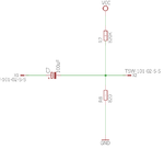
AC Coupling Stage.png

I added this right after JP3. It works well and maintain the waveform signal at 0 axis when read on the oscilloscope. However, when I tried to increase the gain of the signal, it only increase by a few mV. Can anyone tell me whats wrong or is the so called AC coupling DC bias level is wrong ? Is there any better alternatives ? Did I design the right AC coupling stage ?
 

1) what are your voltages? Supply, input, output.
2) You tell us p-p voltage, but what's common-mode voltage? You might be pinned up against your power supply rail.
3) HOW are you adjusting your gain? In the diff amp? In the second stage?
4) what is your frequency? AC coupling is not going to work very well below some frequency.
 

My supply input for this experiment was +/-4.5V and +/-9V.

I am adjusting my gain at the Instrumentation Amp with the 10K pot. I also experimented with increasing the gain at the second stage, but that didn't work too.

My frequency is 150Hz.
 

So basically the AC coupling that I designed is correct ? Or is it a High Pass filter from the the first stage.

I am well aware that the DAQ has no problem with negative input signal. However the problem is that as I increase the gain, the Vpp did not increase but rather, it shifts down the waveform further to negative value.20170208_232724.jpg

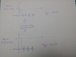
I hope this illustration helps. The reason I wanted to increase the gain is because some DAQ cannot read signals lower than +/- 200mV. In my case, my DAQ could not read any signal since my output is 140mV.
 

Be sure that the first or second amplifier isn't overloaded by DC offsets. In case of doubt, make AC coupling between first and second stage.

I don't understand the purpose of the small DC bias (5 mV or so) in the AC coupling stage. The data acquisition system should have no problem with bipolar input signal, the bias seems pretty useless.

- - - Updated - - -

it shifts down the waveform further to negative value
Suggests to place the AC coupling between first and second amplifier stage.
 

You've got several things going on here. First of all, why put the ac coupling on the output? Second,it appears your amplifier(s) is not working. You adjust the gain, but the gain doesn't change? That's a clue. And what do you mean the DAC won't work below 200 mv? I think you need to first figure out why the amp isn't working-layout problem?
 

Before putting the AC coupling on the output, the amplifiers are working. Without the 2nd stage, the output is only 80mV. The reason I added the AC coupling DC bias level at the output is because, when I increase the gain at AD620, the signal gets shifted down further to the negative side.

Regarding the DAQ, TiePie's minimum input reading range is +/-200mV. I have already tried hooking up my output to the DAQ, and it really cant detect any signal below 200mV.
 

I still think you're misunderstanding your ADC. If you've got an 8 bit adc, and its minimum resolution is 200mv, that would imply a full-scale range of +/- 25V. I don't think that's the case. Regardless, your problem is with your amp. First, if youve got 80mv out of the first stage, you should get about 900mv out of the second, but you said it's 140.

Again, what are your D.C. Levels?
 

I agree that many reported details in this thread don't seem to make sense.

E.g. in post #4 changing the AD620 gain resistor from 8.2 to 2.7 k will about triple the gain, should result in a threefold DC shift and AC signal (as long it's not clipped). Either there's some hidden feedback in your circuit, or the results are not recorded properly.

"cant detect any signal below 200mV" is mysterious as well. Which TiePie device are you actually using? What's the selected input range?

I see that the cheapest HP3 "Handy Probe" has 10 bit (4 mV in lowest +/- 200 mV range) resolution, other devices have 12 to 16 bit.
 

An ECG amplifier has inputs of interference picked up by the patient and other common-mode AC and DC interference produced by muscles in the patient. Therefore the patient's right leg is usually fed a common mode signal out-of-phase with the interference to cancel it when fed to his right leg instead of your ground. It is shown on the datasheet for your AD620 instrumentation amplifier and on many others.
 

Status
Not open for further replies.

Part and Inventory Search

Welcome to EDABoard.com

Sponsor

Back
Top