Continue to Site
Follow along with the video below to see how to install our site as a web app on your home screen.
Note: This feature may not be available in some browsers.
KMoffett said:You would need a PNP transistor ahead of your NPN. Emitter to battery (+), base resistor (100K) to buzzers (-), and collector to a load resistor (10K) to battery (-). Your R1 to the PNP's collector.
Ken
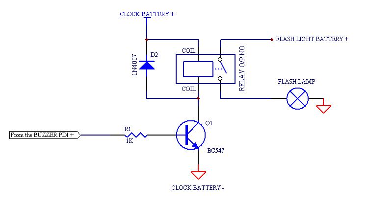
KMoffett said:That circuit may not work. In the battery alarm clocks I've played with, the buzzer's (+) goes to the battery (+). The buzzer's (-) goes to an open collector NPN transistor or N-MOSFET.
Ken
KMoffett said:1. The open collector output is meant to drive a very small load (piezo element) and could not drive a light directly.
Ken
KMoffett said:where are you going to find to relays with 1.5V or 3V coils?
cameo_2007 said:"what is the clock battery voltage.If it is not or more than 5V, then there has to be a slight modification in deriving the coil voltage for the relay."