Continue to Site

Welcome to EDAboard.com

Welcome to our site! EDAboard.com is an international Electronics Discussion Forum focused on EDA software, circuits, schematics, books, theory, papers, asic, pld, 8051, DSP, Network, RF, Analog Design, PCB, Service Manuals... and a whole lot more! To participate you need to register. Registration is free. Click here to register now.

how to compare the two phase difference width for two signals?

Status
Not open for further replies.

xworld2008

Full Member level 4
Joined
Dec 13, 2002
Messages
230
Helped
18
Reputation
36
Reaction score
14
Trophy points
1,298
Activity points
1,801
as below:

signal a______________|-----------------------|__________________
signal b___________________|-------------------------|___________
- Ta - - Tb -

Ta,Tb are less than 100p, Ta, Tb are changing when others signals are changing, How to compare Ta and Tb(Ta > Tb ?)?
no higher clock is available.

Thanks.
 

Yes. now we use two buffer chains which one is smaller, one is bigger. then connect a to small one. b to bigger one. then connect buffer output to FF. then compare the value to two FF groups. this method will take big area. also the setup/hold time will effect the accuracy.
any one have better way?
 

Yes. now we use two buffer chains which one is smaller, one is bigger. then connect a to small one. b to bigger one. then connect buffer output to FF. then compare the value to two FF groups. this method will take big area. also the setup/hold time will effect the accuracy.
any one have better way?
for my information, how you are simulating your design?
 

Hi,

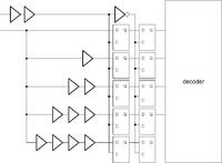
maybe you can do the phase detect with something like in the picture.
You use one input as a clock and the second input as a data input.
You need a unit delay. The clock input is delayed by 2 unit delays.
The data is delayed by 0,1,2,3,4 unit delays. For stability I would latch the output of the 5 input samplers with a second stage (maybe the falling edge of the clock input, assuming your wavetrace is correct)
After that you can use a decoding logic to find the phase


best regards
 

the difference value is less than one unit delay, how can i get the comparison result using this phase detect?
 

Hi,

If your unit delay is larger than the difference, you can not use this circuit.

whats your unit delay? In current ASIC technologies I would assume you can use an inverter which should be around 50ps.

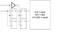
A different approach could be to use every input as a clock and sample the other input (see picture)


if you get a b10 or b01 you can decode which input was first.
if you get b00 or b11 your input are nearly equal.
This depends on the setup/hold of the selected flipflops

regards
 

Thanks, The difference is less that a unit delay(buffer delay), so this is not good way. currently I just use two different size buffer chains, we can utilize the different between two buffers to capture the difference. But this ciruit is too big, I want to find a simple method to do it.

Best Regards,
 

Status
Not open for further replies.

Part and Inventory Search

Welcome to EDABoard.com

Sponsor

Back
Top