Continue to Site

Welcome to EDAboard.com

Welcome to our site! EDAboard.com is an international Electronics Discussion Forum focused on EDA software, circuits, schematics, books, theory, papers, asic, pld, 8051, DSP, Network, RF, Analog Design, PCB, Service Manuals... and a whole lot more! To participate you need to register. Registration is free. Click here to register now.

How to build a voltmeter using Pic16f887?

Status
Not open for further replies.
Re: Volt Meter Pic16f887

Code:
           [COLOR="#0000FF"]ADCResult = (ADC_Read(0) * 500) >> 10 [/COLOR]
           voltage[0] = ADCResult div 100 
           voltage[1] = (ADCResult div 10) mod 10 
           voltage[2] = ADCResult mod 10 
           display[0] = voltage[0] + 48 
           display[2] = voltage[1] + 48 
           display[3] = voltage[2] + 48 
     vout: 
           LCD_Out(1, 10, display) 
           delay_ms(50) 
     wend 
end.
Here what does this line mean to do 
 [COLOR="#0000FF"]ADCResult = (ADC_Read(0) * 500) >> 10[/COLOR]?

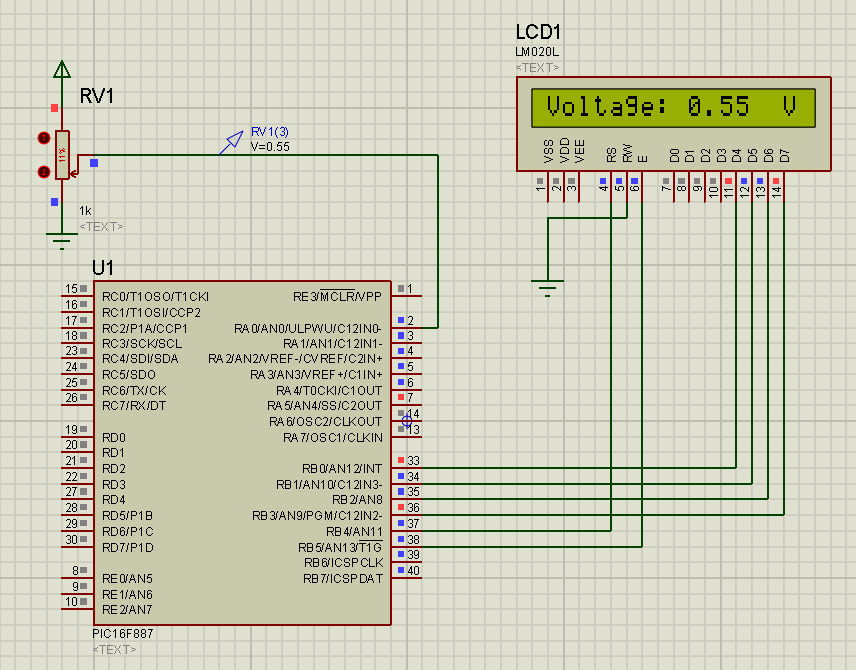
its display result are VOLT (RMS Value) or VOLT (PEAK Value) ???
 

Re: Volt Meter Pic16f887

Hi lacoste,

I present here a simple voltmeter with 16F887 (0-5v scale). But mind it, this is very basic with no input overvoltage protection. A voltage greater than 5v applied to the input will destroy the 16F887.

Source code (written in mikroBasic):
Code:
program softwarefor887Voltmeter

dim LCD_RS as sbit at RB4_bit
    LCD_EN as sbit at RB5_bit
    LCD_D4 as sbit at RB0_bit
    LCD_D5 as sbit at RB1_bit
    LCD_D6 as sbit at RB2_bit
    LCD_D7 as sbit at RB3_bit

    LCD_RS_Direction as sbit at TRISB4_bit
    LCD_EN_Direction as sbit at TRISB5_bit
    LCD_D4_Direction as sbit at TRISB0_bit
    LCD_D5_Direction as sbit at TRISB1_bit
    LCD_D6_Direction as sbit at TRISB2_bit
    LCD_D7_Direction as sbit at TRISB3_bit

dim ADCResult as longword
dim voltage as word[5]
dim display as string[5]

sub procedure GlobInit
    ANSEL = 1
    ANSELH = 0
    TRISA = 1
    TRISB = 0
    PORTB = 0
    LCD_Init()
    LCD_Cmd(_LCD_CLEAR)
    LCD_Cmd(_LCD_CURSOR_OFF)
    LCD_Out(1, 1, "Voltage:")
    LCD_Chr(1, 16, "V")
    display[1] = "."

end sub

main:
     GlobInit
     while true
           ADCResult = (ADC_Read(0) * 500) >> 10
           voltage[0] = ADCResult div 100
           voltage[1] = (ADCResult div 10) mod 10
           voltage[2] = ADCResult mod 10
           display[0] = voltage[0] + 48
           display[2] = voltage[1] + 48
           display[3] = voltage[2] + 48
     vout:
           LCD_Out(1, 10, display)
           delay_ms(50)
     wend
end.


Hi Tahmid,


Is it really working or just for fun?
 

Re: How to build a voltmeter using Pic16f887

It should work. Check this image:

1440788100_1373997438.png


Try to make the circuit yourself again. If you still can't do it, I'll attach the DSN file. But it's a really simple simulation and you should be able to do it easily.

Hope this helps.
Tahmid.


But this is only for meassure 5 V DC only?


Regards
 

Re: How to build a voltmeter using Pic16f887

But this is only for meassure 5 V DC only?


Regards

Yeah, I mentioned that in the post where I gave the code. You can change the range just by scaling (for example using a voltage divider and buffer, if necessary) and adjust the code to reflect the change required in the display.
 
Re: Volt Meter Pic16f887

an u post hear source code [asm or hex ] file also ?
 

Status
Not open for further replies.

Part and Inventory Search

Welcome to EDABoard.com

Sponsor

Back
Top