Continue to Site

Welcome to EDAboard.com

Welcome to our site! EDAboard.com is an international Electronics Discussion Forum focused on EDA software, circuits, schematics, books, theory, papers, asic, pld, 8051, DSP, Network, RF, Analog Design, PCB, Service Manuals... and a whole lot more! To participate you need to register. Registration is free. Click here to register now.

How to build a fixed switching frequency hysteresis controller for buck converter?

Status
Not open for further replies.

helenpenghan

Newbie level 4
Joined
Jan 16, 2008
Messages
7
Helped
0
Reputation
0
Reaction score
0
Trophy points
1,281
Activity points
1,343
Hello,
I am trying to build a hysteresis control for very high frequency DC-DC converter. However, one drawback of hystersis comparator is the variable switching frequency with different outputs. I need a fix switching frequency for the whole system to ensure certain bandwidth. Is there any analog solution for a fixed switching frequency hysteresis control? Thank you.
 

Well, if you used a fixed frequency converter, then it is no longer an hysteretic converter :) The 'bang-bang' regulation, is where the output voltage directly controls the switching frequency. Once you use an hysteretic converter with an external control loop (such as external PWM in the feedback) then you are essentially changing the converter type.

I would strongly recommend a different control topology. Unless you require fast load step, there are plenty of integrated devices which can serve your purpose, and are generally much more straightforward to work with.
 

Hysteretic control effectively introduces a 'delay' into the control loop to achieve self oscillation. I believe that at 50% duty cycle your switching frequency will be it's maximum at reciprocal of 4 times the delay time. Either side and it will drop. The hysteresis, amongst other things sets that delay time. Larger hysteresis gives more delay and vice versa.

In order to 'fix' the frequency you might consider varying the hysteresis based on duty cycle, reducing it either side of 50% duty cycle. That may not be 'precise' over wide ranges of operation but it would be 'simple'. Otherwise you might 'go for it' and use a Phase Locked Loop fed with your target frequency and the converter frequency to adjust the hysteresis to a required and exact value. Of course then you get into the realms of stability of that loop and jitter within it. I have modelled such a system and it does work.

There is also... some 'direct injection' technique as described by International Rectifier somewhere where an external clock is used to force an audio amplifier to 'lock' to its frequency,

International Rectifier - Application Notes
http://www.irf.com/technical-info/appnotes/an-1138.pdf

Page 4 of the above PDF and they may mention the technique in other design/application notes.

Genome.
 

Are you talking about hysteresis control of the output voltage, or hysteresis control of inductor current? If the latter, then you can not have fixed frequency with a fixed hysteresis gap. If you modulate the hysteresis, then you'll probably introduce stability issues, which kind of defeats the point of hysteresis control in the first place (good open and closed loop stability).
 

i believe the mc34063(?) chip implements fixed frequency , burst mode control, which is not quite hysteretic control, but it is a simple and very , very cheap chip.

i found they tended to need large output capacitance to get rid of low-ish frequency output voltage oscillations.

since they only use a comparator to regulate the vout, the comparator of course has a high impedance input, which makes them prone to noisy operation, with very irregular switching currents.......you can in some way mitigate this with a ~100pF capacitor on the comparator pin, but too much capacitance here and you get vout oscillations.

mind you , if the vout oscillations are tolerable to your circuitry, then who cares about them?
 

Going off on a flight of fantasy then let's say you want to do 12V out with 24V in, 50% duty cycle, with a 100mA minimum load current. Ripple current in your inductor needs to be 200mA. 1MHz gives you 500nS set/reset at 12V so your output inductor works out to be...

L = Vsr.Tsr/dI

L = 12*500n/200m

or 30uH

The ripple current will be a triangle wave and get converted to a triangle voltage across your output filter ESR. Assuming +/- 10mV hysteresis in your driver then you would want 10mV/100mA or 100mR of ESR in the filter capacitor..

Let's see if that rocks... and surprisingly it does because, after babbling sums, I have just had a look,


A1 is the 'driver' with its hysteresis, Vh, set to 10mV. Other components more or less as suggested. Fundamentally, perhaps, you need to maintain the 'loop' first order and that is the inductor driving the filter capacitors ESR. As such that signal, at the switching frequency, needs to be delivered 'undisturbed' to the input of your 'driver'. That will be R2 and C1..


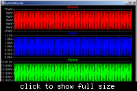
Summing point to the 'driver' is 10mV peak, its hysteresis. Output voltage shows the same, 'AC', peak levels. That will be R2 and C1 delivering. Ripple current in the inductor is 200mA peak to peak.

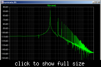
And the switching frequency is...


1MHz.... I was surprised as well.

I think I'm still right about a 'delay time', which you will have in circuit, having twice the effect.. just 'learnt' something new myself in regard to hysteretic control.

Otherwise it is just a model which demonstrates some of the underlying principals. No doubt in real life things will be much harder.

LTSpice Model attached if you wish to play.

Linear Technology - Design Simulation and Device Models

Try setting the output voltage to other levels above and below 12V and see how it affects the operating frequency. Wet finger in the air says +/- the same either side of 12V/50% duty cycle will give the same reduction in operating frequency.

As suggested you can bring it back by reducing the level of hysteresis in the 'driver'. Assuming you can control it then I don't imagine that the disturbances and time scales over which they occur that you might be expecting to deal with will upset the overall operation.

There may be other 'niceties' but unless you were already there it's a start.

Genome.
 

Attachments

  • hyststarta.zip
    1 KB · Views: 68

Status
Not open for further replies.

Similar threads

Part and Inventory Search

Welcome to EDABoard.com

Sponsor

Back
Top