Continue to Site

Welcome to EDAboard.com

Welcome to our site! EDAboard.com is an international Electronics Discussion Forum focused on EDA software, circuits, schematics, books, theory, papers, asic, pld, 8051, DSP, Network, RF, Analog Design, PCB, Service Manuals... and a whole lot more! To participate you need to register. Registration is free. Click here to register now.

[SOLVED] How do I design my IR circuit for digital input.

Status
Not open for further replies.

PoS080

Junior Member level 3
Joined
Apr 2, 2017
Messages
26
Helped
0
Reputation
0
Reaction score
0
Trophy points
1
Activity points
243
Hello EE friends,

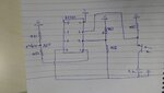
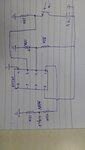
I am working on an IR circuit using an IR photodiode and photoresistor. I want to pick up a LOGIC 1 if the phototransistor is ON and a LOGIC 0 if the phototransistor is off.

Currently I am using a LED attached between the emitter and ground to tell the state of the phototransistor, but I believe in my final design I should use a resistor for better control over the voltages. Please see the simulation image below of the on and off states of my circuit.

The left most circuit simulates my micro with which is running the IR diode. The middle circuit shows my current set up for the receiver circuit using an LED, and the right most circuit shows the receiver with a resistor instead of an LED.

My micro senses anything above 1.5 volts as a logic 1, I am picking up the signal at the blue nodes.

IRL, I do not get 5.77 volts at node '1' i get close to 0.45 volts.

V2 = 9 volt battery


offstate.png

onstate.png

My questions are
1. Am I picking the signal up at the right place?
2. Is there a better way to design for signal pick up?

**note to mods: I dont think this is a micro question, since I'm not asking about mircros but about circuit design for my receiver, but if this is in the wrong place I apologize in advance**
 

Hi,

Why did you choose 120 Ohms. It needs about 40mA of phototransistor current to get 5V.
--> use a higher value resistor.
Maybe 1k ... 10k.

It is very likely that you encounter some problems with ambient light.
The try to eliminate ambient light with a tube.
Or use a modulated LED signal and a demodulator at the receiver side.

Klaus
 

I will try this tomorrow when I go back to the lab.

I was also wondering if I could use an op-amp here has a comparator?
 

Hi,

For high speed you need a low value resistor. But then you get low voltage.
Then a comparator may be useful

***
My opinion:
If you want to amplify a signal to get an analog output, then use an OPAMP.
If you want to compare a signal to get a digital output, then use a COMPARATOR.

Both have good availability, but each is optimized for it´s job.

Klaus
 

So should I use a low value r2 and then connect it to a comparator?

Also I only have op amps which i can put into a comparator configuration.
 

Okay i have used a dmm and i get .08 volts for my high and .00 for my low. How would i go about raising the voltages to detectable levels? Op Amp or comparator? Config?
 

Hi,

Why now 0.08V only? What did you change?

As already said above: if you want digital output, then I recommend a comparator.
Select the threshold at 50% between low_value and high_value.

Klaus
 

I did not change anything those are the values in getting.

Thw drops dont make sense, i think my transistor is not working properly.

9v to collector, red led with 120 ohm resistor to emitter , ground. Is my current circuit. Resistor is on led cathode so i can measure the drop after led.

I also have bjts that i could use for switching.
 

Try connecting circuit as per this diagram
 

Attachments

  • 14919146685031443245762.jpg
    14919146685031443245762.jpg
    503 KB · Views: 110
  • 14919148272701556141791.jpg
    14919148272701556141791.jpg
    501.8 KB · Views: 108
  • Like
Reactions: PoS080

    PoS080

    Points: 2
    Helpful Answer Positive Rating
Hi,

red led with 120 ohm resistor to emitter
Resistor is on led cathode so i can measure the drop after led
Both is not shown in your schematic...

IRL, I do not get 5.77 volts at node '1' i get close to 0.45 volts.
Now you say 0.08V only.

What is correct now?
Show your current schematic so we can talk about.

Klaus

- - - Updated - - -

Hi,

your battery connection is wrong. One leg is GND the other VCC.
Connect VCC to the collector.

***
Don´t let unused inputs floating.
Connect them in a way that you have a predictive and stable output.

Klaus
 
  • Like
Reactions: PoS080

    PoS080

    Points: 2
    Helpful Answer Positive Rating
IMG_20170411_221443481.jpg
With few corrections. I hope this might work
 
  • Like
Reactions: PoS080

    PoS080

    Points: 2
    Helpful Answer Positive Rating
Thanks Klaus and Pacman.


Turns out one of my parts (IR diode) was partially damaged internally. After switching it out, I was able to pick up the input with this circuit. I replaced the RED LED with a regular .7 drop diode and added a 10k resistor as advised earlier. this was enough to toggle a logic 0 and 1 on my micro.

@ PacMan Thanks for the design, I will be using it in another stage.
Screenshot_3.png
 

Status
Not open for further replies.

Similar threads

Part and Inventory Search

Welcome to EDABoard.com

Sponsor

Back
Top