Continue to Site

Welcome to EDAboard.com

Welcome to our site! EDAboard.com is an international Electronics Discussion Forum focused on EDA software, circuits, schematics, books, theory, papers, asic, pld, 8051, DSP, Network, RF, Analog Design, PCB, Service Manuals... and a whole lot more! To participate you need to register. Registration is free. Click here to register now.

How did I kill 2 Mosfets?

Status
Not open for further replies.

ants

Full Member level 4
Joined
Feb 20, 2010
Messages
199
Helped
1
Reputation
2
Reaction score
0
Trophy points
1,296
Location
UK
Activity points
3,006
I had a board made up for me, it came in good order but being a novice at circuit design I always make a mistake or two...it is a piezo driver that includes a DC booster, the Max770. I made up the first circuit and crossed my fingers that it would work, the DC booster did work for a while but then I saw a little puff of smoke and it died, i checked the heat of it and it burnt my finger. I made up the DC booster part of the second board with nothing else on it and the same thing happened. Before it died the second time I was able to check the output readings, I was inputting 6V and getting about 18V out, as expected, the odd thing there was that the output seemed too variable for a DC booster, it was actually varying between 17V and 20V.

Any ideas what happened?

Also the MAX770 is fairly expensive at £4 a chip, as a surface mount component how is it best to get it off the board for reuse?

I've attached the schematic I used and the datasheet.

Thanks,

Ant.
 

Hi ants,

You are configured in bootstrap mode with output in 17 - 18V range.
Maximum input voltage of MAX770 is 16.5V. This could be a problem, maybe try
non-bootstrapped mode. Also Rsense is in milliohms, correct ?
For removing smd chips I use ChipQuik alloy it works great.
Hope this helps.

Cheers,
Scanman
 

If I remember correctly because I was using external resistors to adjust the output voltage the datasheet said I had to use bootstrap mode. R_sense is 50 milliohms. I was wondering if that is too low and it caused some kind of current overload. I will have a look at ChipQuik. If I can find out what is wrong I might still be able to use the circuit by replacing the mosfet.

Regards,

Ant.
 

The power MOSFETs I've seen, do not want more than about 10V
gate drive. What is your FET's rated Vgs (rec max)?
 

Is this on a PCB? Layout can be critical when you have only 50m ohm current sense resistors and high peak currents (4A in your case).

However, I think the most likely cause is using bootstrapped mode, as scanman said. Absolute maximum input is 17V and you have 18V (plus any switching spikes).

I think you have maybe misinterpreted the statement "When using the MAX770/MAX771/MAX772 in non-bootstrapped mode, there is no preset output operation because V+ is also the output voltage sense point for fixed-output operation. External resistors must be used to set the output voltage."

As far as I can see you can run non-bootstrapped with external resistors to set the output voltage.

Keith.
 

The mosfet is the one noted on the max770 datasheet, the Si9410DY, I'm inputting 6V from 4 AA batteries and getting out 18V, I think it should be ok?

I don't need 4A, I was thinking when I selected the value it worked something like the I_limit pins on opamps. But now I'm thinking it works in a different way and it restricts the input of current and I should have kept the current low while testing?

The statement regarding non bootstrapped mode is that which I read. The difference in meaning looks to be created by a comma v. a full stop. That is a good spot!

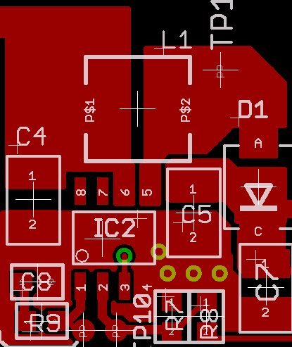
I do have the DC booster on a board I made up with Eagle. The datasheet mentioned a star ground layout so I sent the grounds back to earth on there own traces. I took some care but could have erred. I've attached the schematic and layout. The DC boster part of the board is at the top. The positive input is the via next to the inductor.

Thanks,

Ant.
 

Ant,

I still think the bootstrap is the problem, but you also need to look at your layouts. Maxim don't give suggested layouts, although some other manufacturers do. Typically you would end up with something like this:

54_1281377400.gif


That is a different chip, but should give you an idea. The bottom layer on the PCB is solid ground plane. The problem with your layout is that you could have more than 50m ohms in your tracks. You need to keep them very short and as wide as possible. Let no copper go unused!

Keith.
 

Ah yes. I was getting confused between the input to the circuit, that from the batteries (6V) and the input into the max770 from the mosfet (18V). My layout doesn't look so healthy either :)

Do you use a similar product to ChipQuik? it looks to be a proprietary brand and not available from farnell or RS.

I'm hoping it is the mosfets that have expired rather than the max770's. I haven't had a chance to test them.

I'm debugging the circuit really, it has 4 parts, DC booster, 555 timer, voltage divider and opamp. Not much worked, the 555 timer I have on a stripboard has its output going into a cap which then gives me a dual output both positive and negative. The one on this board doesn't. There is a voltage divider, if I just put a 9V PP3 through it I get +1V and -1V. The big problem here is that I knew I needed a pcb layout for the DC booster but then put all of the other parts on the board without testing them together. I will have to get the 555, voltage divider and opamp working on a stripboard and then make up my next board with the Max in non bootstrapped mode.

Thanks for the input,

Ant.
 

ants said:
Do you use a similar product to ChipQuik? it looks to be a proprietary brand and not available from farnell or RS.

No, I don't know of ChipQuik. Small devices (2 or 3 legs) can usually be desoldered with an iron if you are quick. If not, small side cutters or a craft knife. Cut the legs off then desolder the bits that are left. It obviously ruins the device, but then if you think it's dead it doesn't matter. If it isn't dead and you try with a soldering iron without some practice first you may ruin the PCB. Mind you, even though semiconductors are supposed to only be soldered quickly it is surprising how much abuse you can give them! Just make sure you don't pull too hard until the solder is melted.

Keith
 

I will have a go. I have ruined the first of the boards, I thought it would be worth trying pulling on the chip and lifted the traces. The second is intact so it might be recoverable. I have found a spare n mosfet but not a max770. So it is fingers crossed.

Thanks,

Ant.
 

I have dug out the problem with the 555 not producing a dual output. The 555 needs a resistor as load to ground to take the DC component off. On my board I'd used the wrong connections for the pot used as volume/output of 555 and just shorted it out. I was told what to do in this post:-


I thinking fixing the voltage divider is a matter of trying different values with a 9V battery and see what iworks best.
 

I killed another mosfet. I'm not sure how because I'd changed the resistors to reduce the input to the Max770. Its possible I shorted Rsense and one of the caps, there are too many debug leads and unhappy traces to pursue it further.

The voltage divider was missing a trace to ground. I've debugged it all so this board can now go in the bin :)

Thanks for the input in this thread.

Ant.
 

Did you remove the bootstrapping? I know you reduced the voltage but I think you will have big peaks due to the layout.

When you build your next one I suggest you start with a lot higher current sense resistor until it is working.

Keith
 

I reduced the voltage but didnt remove the bootstrap, I will go to non boostrap for the next revision and increase Rsense for testing.

I will aim for one layer as ground plane and have wide traces, I've not tried this sort of layout and it looks like a fair amount of thought has to go into it. What is likely to cause the peaks?

Thanks,

Ant.
 

The extra inductance due to thin tracks, particularly ground, will introduce all sorts of spikes when things switch.

You need to use polygon fill for the ground layers and also a few small polygons around the regulator and MOSFET.

Keith
 

Hi Keith,

Thanks. I will do this.

Ant.
 

If you have never used polygon fill in Eagle, select it from the icon & select the track width (something small like 0.25mm - it isn't critical) and before you draw it type 'GND' on the command line and hit enter (or whatever net you want it to connect to). You can then draw it and double click to end it. If you forget to set the net name it can be changed after drawing it. You can also edit the polygon after drawing. For high current power supplies I would normally leave thermals "off". Normally you would not want orphans.

Keith.
 

The main problem I seem to have is that I can't find the design rule change to turn off the masks clearance. I'd like pads 4, 6 and 7 of the Max770 (which go to ground) to be connected to the top layer ground plane without the gaps. With the track width at 0.25mm it isn't a big problem routing a lot of the tracks with autoroute on one layer. Thermal isolate seems to be off by default. I will need to add more polygons when I've found the right setting. I will send the next revision this week, so it will probably go with a less than ideal layout, but better than the last board. I will for example tidy up the traces and miter them.

Regards,

Ant.
 

I will give you a proper reply tomorrow when I am at my computer but PLEASE don't use the autorouter!

Keith

Added after 2 minutes:

and the key to a good layout is the component layout. You need to get that right first.

Keith
 

I've made a little progress. I tend to place components then use autoroute, then ripup traces and replace them or then move components.

My target is to get all of the components that go to ground into the top layer ground plane, so I'm growing the ground plane bit by bit.

It is a bit like a bad game of chess were I take back a move and sometimes the last 2 or 3 :)

I will turn autoroute off and see how I go.

Thanks,

Ant.
 

Status
Not open for further replies.

Similar threads

Part and Inventory Search

Welcome to EDABoard.com

Sponsor

Back
Top