steven2410
Newbie level 3
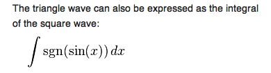
Here is the problem:
 .
.
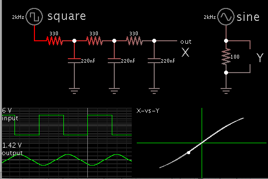
For the 1st one, It's the low pass filter config. However, I think it's not possible to tell so just based on the Input and Output Voltage graph.
2nd one, i actually have no clue.
3rd question, would the Probe be placed on the left hand side of the resistor?
Thank you.
.For the 1st one, It's the low pass filter config. However, I think it's not possible to tell so just based on the Input and Output Voltage graph.
2nd one, i actually have no clue.
3rd question, would the Probe be placed on the left hand side of the resistor?
Thank you.