Vermes
Advanced Member level 4
The project was inspired by **broken link removed**. In this case, the PCB was made again, because of used Russian lamps IW-6 from an old ELWRO calculator, different AC outlet and SMD resistors were applied. The clock operated smoothly from the first run. When LEDs operate smoothly but there are no numbers, you have to change the resistor which powers the ignition fiber. For this purpose it requires 1,2V and 45...55mA. For 5V power it is 70...86ohm (75ohm resistor was removed from an old main board from a computer). Remember to set the lamp once it runs properly. Minimal ignition of the fiber can be seen on turned off lamp in full darkness – normally it can not be seen. The whole fits a board with dimensions of 63x50mm.
And some pictures:
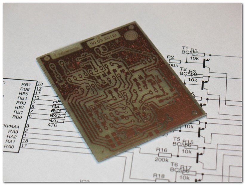
Print and description made in thermal transfer method:
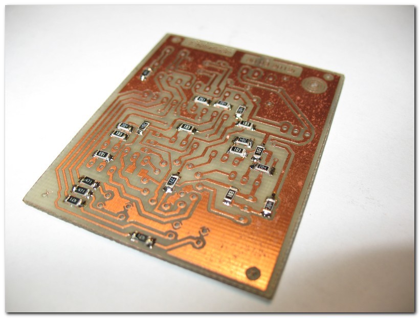
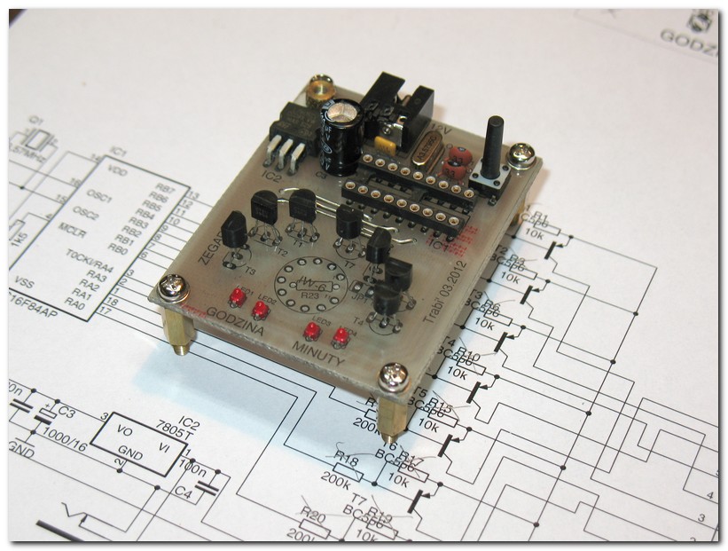
After soldering:
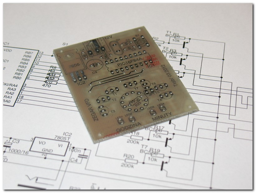
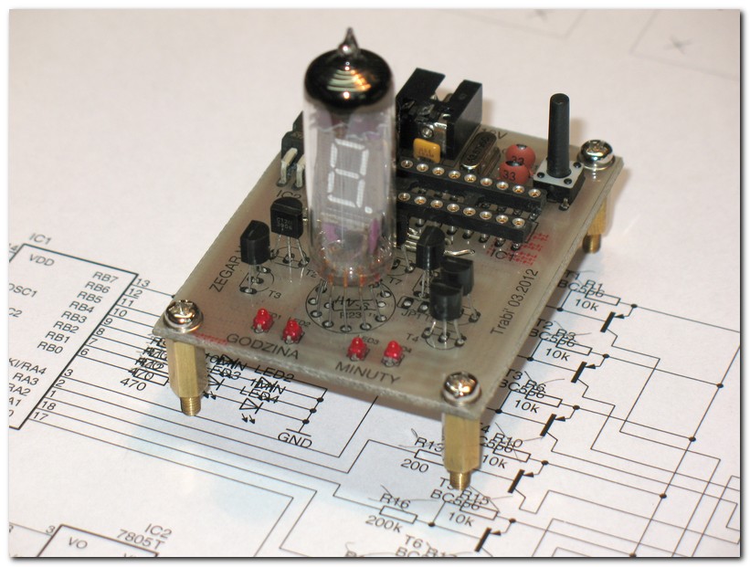
VFD for soldering:
Ready:
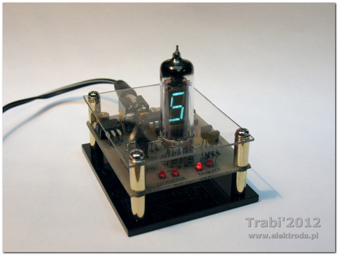
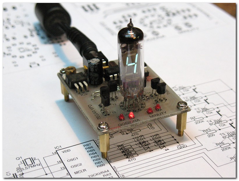
Working:
Link to original thread (useful attachment) – **broken link removed**