Vermes
Advanced Member level 4

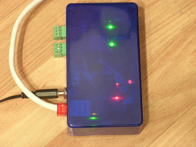
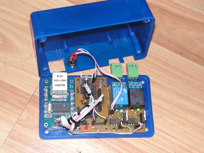
It is a cheap and simple Ethernet switch which is compatible with Arduino. The design is based on similar designs which can be found on the Internet. It is a module construction and uses an Ethernet module based on ENC28J60, processor Atmega328P and relay module with optoisolation. Board for the processor module can be inspired by LINK.
You have to solder stabilizer 3,3V (not included in the schematic) between the ground and output of stabilizer 7805.
Then, perform executive module with separated supply. It can be such as AVT1481.
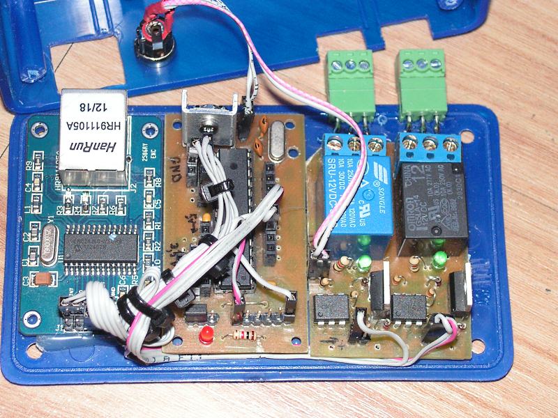
When there are already three modules, they have to be linked. Below you can see the description of connecting pins from the net module for Atmega.
INT to 4
SO to 18
SCK to 19
reset to 1
SI to 17
CS to 16
Vcc to 3,3V
GND to GND
Executive module should be connected to the supply (before the stabilizer 5), and its input to the corresponding pin of Atmega.
Source code to Atmega can be found HERE.
There are codes for two- and four-relay version. Change of IP and MAC can be done by a serial transmission (converter TTL UART). Of course, that requires uploading the Bootloader to Atmega. Below there are PHP scripts for control from Linux.
Link to original thread (useful attachment) - Sterowanie Ethernetowe