Continue to Site

Welcome to EDAboard.com

Welcome to our site! EDAboard.com is an international Electronics Discussion Forum focused on EDA software, circuits, schematics, books, theory, papers, asic, pld, 8051, DSP, Network, RF, Analog Design, PCB, Service Manuals... and a whole lot more! To participate you need to register. Registration is free. Click here to register now.

Hitachi PF08109B power amplifier circuit design

Status
Not open for further replies.

harishyadav

Newbie level 4
Joined
Oct 20, 2015
Messages
6
Helped
0
Reputation
0
Reaction score
0
Trophy points
1
Activity points
51
Dear sir,
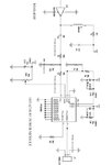
I am using Hitachi PF08109B power amplifier.
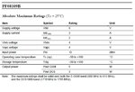
i am providing Vapc (Pin no. 10,Max. ratings: 2.2V , 3mA) to the Power amplifier using a voltage divider circuit.
The open circuit voltage is set to 2.5 but once connected it drops to .9V dc.
Is it a current consideration ?
Why the voltage is dropping when connected in the circuit?
 

You forgot to post its schematic.
What is the function of Vapc?

If you load a voltage divider then its voltage normally drops unless the current in the voltage divider is much more (>10 times) than the load current. Then what was the current of your voltage divider?
 

    V

    Points: 2
    Helpful Answer Positive Rating
You forgot to post its schematic.
What is the function of Vapc?

If you load a voltage divider then its voltage normally drops unless the current in the voltage divider is much more (>10 times) than the load current. Then what was the current of your voltage divider?


-Reply from harish :


Dear sir
i have posted an image of the circuit in which power amplifier PF08109B is used .
The pin of my concern is pin Vapc(GSM) (control voltage, Pin no.10).
 

Attachments

  • Clipboard03.jpg
    Clipboard03.jpg
    22.8 KB · Views: 129
  • PF08109b pin diagram.jpg
    PF08109b pin diagram.jpg
    45.7 KB · Views: 112
  • PF1089b pin schematic.jpg
    PF1089b pin schematic.jpg
    102.5 KB · Views: 90

Hi,

Your voltage source from the pot is weak.
A 10k pot has an output resistance of 0...2.5kOhms (in your configuration).

The datsheet doesn't say the input current is constant, therefore I sassume it varies.
If it varies from 1mA to 2mA...this may cause a voltage drift of 2.5V.

--> I'd use an amplifier to generate a low impedance voltage source.

Klaus


Reply from harish yadav,


Dear sir,
As suggested by you,
Please suggest a suitable circuit of an amplifier generate a low impedance voltage source .
 

Hi,

almost any "non inverting OPAMP circuit" will do. Gain = 1.


Klaus
 

Many opamps do not work from a low power supply voltage and have inputs and outputs that cannot go down to only 2.2V.
 

Dear sir,
I am using RF section circuit (attached below) in my Mobile jammer project:

1. I am not able to find "50 ohm Micro strip" that is used for impedance matching.Please suggest a solution for "50 ohm micro strip" or any other alternative for impedance matching.

2.Which online RF circuit simulation tool is good in order to check the circuit output?
 

Attachments

  • Clipboard03.jpg
    Clipboard03.jpg
    22.8 KB · Views: 81
  • PF1089b pin schematic.jpg
    PF1089b pin schematic.jpg
    102.5 KB · Views: 82
  • PF08109b pin diagram.jpg
    PF08109b pin diagram.jpg
    45.7 KB · Views: 91

A Mobile (cell phone) jammer is illegal (it will block somebody calling for an ambulance, a fire brigade or calling the Police) so we should not help you with it and this thread should be closed.
 

Hi,

The thread is going into a wrong direction.

We don't want to support the design of illegal circuits.
Therefore we decided to close the thread.
 

PF08109B power amplifier

Dear sir,
This is my final year academic project. i have no such planning as quoted by you.
This is only for academic purpose.
The same problem i had with Modem Design.
Rest assured that i have no such intentions.
 

O.K. Thread re-opended. Please no further discussions about GSM jamming, e.g. technical details how to achieve it.
 

Status
Not open for further replies.

Similar threads

Part and Inventory Search

Welcome to EDABoard.com

Sponsor

Back
Top