Continue to Site

Welcome to EDAboard.com

Welcome to our site! EDAboard.com is an international Electronics Discussion Forum focused on EDA software, circuits, schematics, books, theory, papers, asic, pld, 8051, DSP, Network, RF, Analog Design, PCB, Service Manuals... and a whole lot more! To participate you need to register. Registration is free. Click here to register now.

High voltage PSU Mosfet choice

Status
Not open for further replies.

MarcusFunt

Newbie
Joined
Aug 20, 2022
Messages
4
Helped
0
Reputation
0
Reaction score
0
Trophy points
1
Activity points
44
Hi!

I am building a device for a national competition ("Unge forskere") That should be able to sterilize hands with nothing but electricity.

For this project, I need a High-Voltage power supply, capable of delivering 12(or so)kV at 30-100khz.
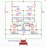
Therefore my head automatically went to the very popular "ZVS driver" because I want a very efficient operation without much heat as it will be placed in a closed box.
You can look at my current schematic in the attached picture.
I modeled the schematic in lTSPICE and found that 71v spikes occur at startup, and therefore can't use the 60v IRFZ44N I originally wanted to use.
Now the problem is that I don't know what other MOSFET I can use.
I don't care if it is SMD or THT.
I found a few FETs I think will work, but I'm not certain

FDP085N10A-F102​

NTP011N15MC​


Any help, both with MOSFET choice and flaws in my design is greatly appreciated
 

Hi,

I can´t find the attached schematic.

MOSFETs are selected by oltage, current, R_DS_ON, speed parameters ....
And for this distributors as well as the MOSFET manufacturers provide selection tools.
Use them.

Althow: "national competition", "sterialize hands", "12kV", "without much heat", "closed box" maybe are good side informations .... one still need to know the electric specifications to choose the right one.

71V spikes on Ltspice:
If you are not an experienced PCB layouter fro SMPS you will see a much higher spikes on the real circuit. On the other hand one may suppress them to a lower level with a suitable circuit.

Klaus
 

Hi Klaus. Thank you for your swift reply. I am very new to this website, therefore I couldn't figure out how to attach the picture. it should however be attached to this post.
I am switching the FET at 70khz, so I need a relatively low gate capacitance, but more importantly, my RDS needs to be low because of limited cooling opportunities. I am not a very good pcs layout engineer, so I chose 100v for my MOSFETS as well as TVS diodes across the drain and source of my FET.
I am not sure what FET I am going to use yet, so any ideas are very appreciated.
 

Attachments

  • Screenshot og zvs schematic.PNG
    Screenshot og zvs schematic.PNG
    28.7 KB · Views: 126
Last edited:

My input voltage will be 12vdc from a commercial smps. but the voltage across the MOSFET is dependent on the resonant circuit formed by the primary coil and resonant capacitor. the resonant voltages and current are calculated by LTSPICE: 17A peak. 42vac peak. I will at max be drawing a few milliamps from the transformer.
The MOSFETs will however only pass around 10A max.
The gates will be getting 12v protected by Zener's and flyback diodes(probably not necessary)
the inductance of my primary is going to be around 3-6microheny(very vague I know)
 

It seems unlikely you will ever get 12kV ac @ 70kHz, as the capacitance in the Tx will dominate - and unless it is carefully section wound it will flash-over internally, just as an example 100pF @ 70kHz = 22.7 k ohms
= 520mA rms at 12kV rms = 6.333kVA circulating in the PSU = 213 amps AC circulating in the 333nF cap on the 12V side ... ( assuming 42Vpk = 29V rms on this cap ).
 
Easy P is quite right, a conventionally driven transformer is just not going to be practical.

You may need to think more along the lines of a single layer air cored self resonant inductor, something similar in principle to a mini Tesla coil perhaps ?
 
Last edited:

That is an excellent way to wind a high voltage transformer for individual pulses, and its commonly used in igniters for gas appliances and coil on plug car ignition systems. It will work very well, but only at fairly low repetition rates, probably up to only a very few few Khz.

Once you start winding coils with a large number of turns in each section of the bobbin, the self resonant frequency rapidly decreases, and the chances of voltage breakdown increases. To improve all this requires more and more smaller bobbin sections, each with fewer turns. The ultimate progression leads up to a single layer fairly long winding.

If you just wanted individual 12Kv pulses (or dc) that is dead easy.
Constant ac output at 70 Khz is a very different requirement, and far more difficult.
--- Updated ---

Here is a fun toy to play with.
https://www.aliexpress.com/item/32987629991.html
 
Last edited:

A standard tesla coil's output current is way too low for what I need. combine that with 30 times too high frequency (for the one you linked) and an efficiency of less than 8 percent. I am not able to use an air-core transformer/tesla coil. The section bobbin approach is the best one for me since I have a 3d printer, experience with creating high-voltage high-frequency transformers, and access to oil and a vacuum chamber. I don't even need the 70 KHz, some recent calculations I made show that 30 kHz is enough. CRT-TVs, arc lighters, LCD tv, air ionizers, and microwave ovens all have a power supply similar to the one I am making. The hardest part for me is making the drive circuitry.

But thank you guys for the feedback anyway:)
 

I would suggest 20kHz or even lower - if you can hear 15kHz this is a great safety feature ( i.e. you can hear when it is going )

You need to measure the SRF of the finished Tx, if it is too close to the intended operating freq you will have issues of circulating current and high losses ...

again, getting a true 12kV ac at high freq is problematic, ( 12kV rms sine = 17kV pk )
--- Updated ---

In the driver ckt shown in post #1 the 333nF cap will have to carry real ac current, so several caps in // may be required, the freq is set by this cap and the effective L of the primary, the 50uH chokes should be large enough to keep the current ripple to < 30% and not saturate at the high currents needed. The calcs are straightforward.
 

CRT-TVs, arc lighters, LCD tv, air ionizers, and microwave ovens all have a power supply similar to the one I am making. The hardest part for me is making the drive circuitry.
None of the power supplies for the above examples you give produce high voltage high frequency sine waves.

Good luck with your project.
 

Status
Not open for further replies.

Similar threads

Part and Inventory Search

Welcome to EDABoard.com

Sponsor

Back
Top