Continue to Site

Welcome to EDAboard.com

Welcome to our site! EDAboard.com is an international Electronics Discussion Forum focused on EDA software, circuits, schematics, books, theory, papers, asic, pld, 8051, DSP, Network, RF, Analog Design, PCB, Service Manuals... and a whole lot more! To participate you need to register. Registration is free. Click here to register now.

High Side switching using P Channel

Status
Not open for further replies.
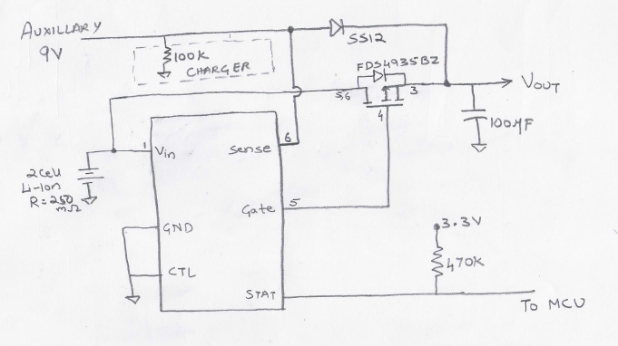
Capacitor Used: 100uF
100KOhms connected to SS14 anode and Ground

Outputs

With Battery

Without Auxillary: Battery Voltage: 7.77V, Gate Voltage: 7.61 V, Stat: 3.26V, Output: 7.61V

With Auxillary: Auxillary Voltage: 9.42V, Gate Voltage: 9.11, Stat: 137mV, Output: 9.31V

Without Auxillary, the MOSFET should be ON but the gate never goes to 0V
 

Hi,

Without Auxillary: Battery Voltage: 7.77V, Gate Voltage: 7.61 V, Stat: 3.26V, Output: 7.61V

At this state measure all voltages on all six pins of the LT4412 and tell us. Directly at the IC pin, not the pad. All referenced to PCB GND.

***

You have not other connections or parts added or missing? It is exactely like in your shown schematic?

Klaus
 

When only battery is present (without Auxillary)

Vcc: 3.3V with 470K Pullup at STAT

Battery Voltage: 7.77V

LTC4412 PINS
Vin = 7.77V
PIN 2 and 3 = GND

STAT: 3.28V
GATE: 7.61V
SENSE: -7mV

- - - Updated - - -

When battery is present (with Auxillary)

Vcc: 3.3V with 470K Pullup at STAT

Auxillary Voltage: 9.42V
Battery Voltage: 7.77V

LTC4412 PINS
Vin = 7.77V
PIN 2 and 3 = GND

STAT: 140mV
GATE: 9.12V
SENSE: 9.42V

- - - Updated - - -

SCH I AM USING


- - - Updated - - -

VOUT Connected to CRO
 

I have checked the MOSFET separatly and its working fine.

LTC4412 STAT Pin changes and I suppose that is working too..

I have crosschecked the schematic on board and there is no connectivity issues at all...

Everything is inline with the schematic shown

Should I be using a pull down on gate pin? Not sure on this... Any suggestions?


Used Pull down on gate pin... same results


I did change the IC... yet same results...

- - - Updated - - -

Latest Update:

I disconnected the track between gate of LTC4412 and gate of the MOSFET and these are the observations.

The LTC4412 gate pin shoots between 9V (when auxillary power connected) and 550 something mV when removed. Ofcourse battery being always connected.


The gate (open - Not connected) at MOSFET is at 7.75V when only battery is connected
When Auxillary power connected it shoots up to 9V

So the LTC4412 is working.

Any suggestions why I am seeing the voltage at gate of MOSFET even when open (Not Connected)
 
Last edited:

Hi,

When only battery is present (without Auxillary)
...
SENSE: -7mV
This can not be. SENSE = the LOAD voltage. Even the FET internal body diode should make it about 7.2V
Either FET is defective, or it is bad wired, or SENSE connection is bad wired.

****
When battery is present (with Auxillary)
...
Auxillary Voltage: 9.42V
...
SENSE: 9.42V
This can not be, there must be a voltage drop. --> bad wiring.

Klaus

- - - Updated - - -

Added:

Just saw your schematic:
There is the mistake. You connected SENSE to the auxiliary input instead of load.

I checked LT´s datasheed. I´d say Figure3 has wrong wiring. On every other Figure SENSE is connected to the load.
Please try to connect SENSE to load.


Klaus
 

...................
Just saw your schematic:
There is the mistake. You connected SENSE to the auxiliary input instead of load.

I checked LT´s datasheed. I´d say Figure3 has wrong wiring. On every other Figure SENSE is connected to the load.
Please try to connect SENSE to load.
That schematic is correct.
If you read the description right above Figure 3, it describes how they are using the chip as a comparator and not in the linear mode as with the other configurations.
My simulation of that configuration also works.
 

Hi,

@crutschow
You are right. I should have spent more time to read through the datasheet. There is a description for this schematic.

But I'm curious, what happens when SENSE is connected to the output.

Klaus
 

The SENSE will be low when only battery is connected as its not connected to the load.

I have tested various scenarios for 4412 and its working fine

Battery only Present : STATUS = 0 (almost), GATE = 0, STAT = 3.3V (Ideally MOSFET should turn ON now)

When Auxillary also present: STATUS: 9V (Almost), GATE: 9V, STAT = 0V


PROBLEM is the MOSFET side

When only Battery Present

MOSFET GATE: 7.77 V

When Auxillary also present: MOSFET GATE shoots up to 9V


Note: The gate of MOSFET is not connected gate of 4412 and its open. (I am doing it to check the MOSFET Part)
 

Note: Not connecting Gate of 4412 to gate of MOSFET

Tested 4412 separatly and its working

Tested MOSFET seperatly and its working (GND and VCC to GATE changed by external Source)

Guess the gate pin of 4412 is not able to drive the MOSFET

wondering what could be the reason.
 

Check the resistance between the MOSFET gate and both the source and drain.
It should be many megohms.
 

Update.

Had almost given up on this circuit and had left it the way it was on my desk for last two days.

Today morning when I turned it ON (with no changes made at all), It seems to be working fine... I am completely puzzled why this was the case.

Till now its working fine. Let me see how it goes.


Meanwhile when auxillary is connected, will there be any voltage at the drain. According to the body diode details there shouldnt be but I see some voltage there, even when battery is removed.

Diode reverse bias??? Cant be at 9V
 

Status
Not open for further replies.

Part and Inventory Search

Welcome to EDABoard.com

Sponsor

Back
Top