Continue to Site

Welcome to EDAboard.com

Welcome to our site! EDAboard.com is an international Electronics Discussion Forum focused on EDA software, circuits, schematics, books, theory, papers, asic, pld, 8051, DSP, Network, RF, Analog Design, PCB, Service Manuals... and a whole lot more! To participate you need to register. Registration is free. Click here to register now.

Help with circuit design.

Status
Not open for further replies.

Malonga

Newbie level 4
Joined
Oct 23, 2014
Messages
5
Helped
0
Reputation
0
Reaction score
0
Trophy points
1
Activity points
70
Hi all,

I am new here so I hope I am posting in the right place.

I am currently working on a uni design project and need some help. The project involves designing and making a circuit which will drive a small motor forwards or backwards depending on the temperature.

This is my design so far,
circuit.jpg

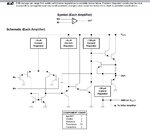
I have decided to use a pair of op amps as comparators with the thermistor being common between the two. The idea is then that the op amps will out put a positive signal when the temperature either goes above or below set temperatures.

This signal from the op amp will then trigger the H bridge to either run the motor forward or in reverse.

I am hoping that someone will be able to have a quick look over what I am planning on doing and tell me if I am going in the right direction. This is my first year at uni and I haven't had a lot of experience with electronics so I am expecting to make a few mistakes along the way.

Cheers,
Craig
 

Transistor switches only provide a current gain of 10 when saturated unless special ultra low Vce parts are selected then - gain of 50 is possible. Mosfets with much lower RdsOn than the coil resistance are preferred in a similar complementary drive.

There needs to be clamp power diodes added to both drivers to protect from large impulses when the motor switch goes ON to OFF and Current Limiting for a stall condition coold be added using PTC's.


This design is now in a single IC called a Bridge Motor driver, with larger motors using at least 1 external power stage, with deadtime control.
 
The input side to the amplifiers is extremely sensitive so any hum pick up or ripple on the supply lines to the thermistor or bias resistors will result in very large pulses being applied to the motor. Also for very small temperature differentials the motor will have , say only 1V across it, so it will not start but will consume current. As there is a very good chance of the motor always stopping at the same point due to added friction in that point of its rotation, the brushes will burn an oxide spot on the commutator, leading to a need for increased volts to start the motor. It would be better if a proper schmidt trigger was incorporated or some form of hysterisis so the motor drive can only be on or off.
I have come across this fault in real life, it only shows its self after some time in service and is extremely hard to localise, as if the motor is vibrated, the brushes find a clean bit of the commutator and then all appears to work.
Frank
 
Hi,

To add the posts of SunnySkyguy and chukey...

my recommendations:
* if you need a comparator then use a comparator.
* If you need an amplifier, then use an amplifier.
* look for a simulation tool to see what happens


*******
To your circuit:
I expect:
* max. half-bridge output voltage = +3.2V
* min. half-bridge output voltage not defined, because low side is never activated
--> motor will not run

Is it correct that you want the motor to run (with rising temperature): backwards ... stop ... forwards?


Klaus
 
I agree that the circuit shown will cause the motor not to run and if it is easily fixed (by removing two useless parts) then the lousy 46 years old design of the 741 opamps reduce the voltage to the motor so it barely runs.
 
Is there some in-between temperature that the motor does not run? Otherwise you only need one op amp.
 

Op Amps cant drive as much current as a selected transistor.

Note this simple example uses a base/collector R ratio of 15.

In this design, never drive both sides high at the same time, otherwise short circuit.
car-radio-receiver.jpg
 

Thanks for the comments and advice everyone,

Is it correct that you want the motor to run (with rising temperature): backwards ... stop ... forwards?

Yes, that is the plan. I was planning on using the two op amps so that I would have a temperature range were the motor would not run in either direction.

Like I said before, I am very new to electronic circuit design so I expect this will take a little while for me to get right but hopefully I will get there in the end. I plan on doing some work on the circuit today and I will hopefully have a revised version by tonight (Aus time).

Once again, Thanks for your help everyone. It is difficult studying engineering by distance but forums like this one really do help.
 

Hi,

If you have experience with ucontrollers, i recommennt to use one.
Thermistor to adc input. Two (maybe one PWM) output to a motor driver IC.

This should give a smaller, more easy and far more flexible solution. Even speed control is possible without additional hardware.

*********
Without ucontroller i recommend to add a capacitor in parallel to the thermistor to avoid AC pickup.
The comparator inputs i'd do wit a series connection of three resistors. Connect the two comparator inputs at the two connections of the center resistor. (With the center resistor you can adjust the STOP area.)
Capacitors to stabilize voltages and hysteresis on the comparators will give more satisfying results.
I recommend to use a motor driver IC. Use one with self protection (free wheeling diodes, overvoltage-, overcurrent- and overtemperature protection)
If you give the motor data we can help to choose one.

Klaus

Hi Klaus,

Thanks for taking the time to give me advice, I really do appreciate it.

Part of this project is students using the concepts that we have learnt through the semester so far. This includes only basic analog circuits that can be assembled on breadboards so I think ucontrollers are out of the question.

Bit of an update on what I am planning on doing. I have decided to do away with the op amps and instead try and use a TI LM339 quad comparator.

https://www.ti.com.cn/cn/lit/ds/symlink/lm339-n.pdf

I think that it will be a more appropriate for what I am trying to achieve as well as making the circuit a bit more streamlined.

I haven't made much progress with the H-bridge and am still trying to get my head around which transistors I should use, so if anyone has a article on H-bridge design I would be grateful if they could share it with me.

I built my original design just to see what the results would be and I found that you guys called it. It was a resounding failure. The motor was drawing a current but there wasn't the voltage to get any kind of movement.
One up side was that I did take some measurements of the thermistor and was able to calc the values for the resistors for the reference voltages.

A little about the motor.

**broken link removed**

I did a no load test at 9V and it was drawing .193A which is how I plan on running it in the circuit.

I have the day off work tomorrow so I will spend some time getting my head around transistor and will hopefully get a new circuit diagram done by late arvo.

Once again, Thanks for the help,

Craig
 

read the motor specs again.

12V 8,100 RPM DC Electric Motor

• Torque 180 g.cm
• Voltage (V): 12

NO LOAD
• Speed (rpm): 14500
• Current (A): 0.28

AT STALL
• Torque (g.cm): 372
• Current (A): 5.21

AT MAX EFFICIENCY
• Efficiency(%): 66.1
• Power (W): 5.56
• Speed (rpm): 13544
• Torque (g.cm): 40
• Current (A): 1

AT MAX POWER
• Output (W): 13.57
• Speed (rpm): 8266
• Torque (g.cm): 160
• Current (A): 2.4


A Bridge is simply a bi-directional switch where the heat rise of the switch depends on the voltage drop * current * thermal resistance Rja 'C/W (read Resistance junction to,ambient in Celsius or Kelvin K/W ) or degree rise per watt for the duration depending on thermal mass and duration of power.

1st you need a power supply that can deliver 12V after bridge losses. Power loss heat rise is a mechanical concern.

Bridge Losses can range from <0.1V to several volts depending on parts selected. One might consider <0.5V per driver for Vce or >0.7V for Vbe in emitter followers.

MOSFETS with low RdsOn are preferred. ( meaning Resistance of switch when on between Drain and Source like Collector and Emitter in BJT's.

Then choose a suitable gate threshold or biasing for commutating , so only 1 Polarity is ON at a time to prevent shoot-thru failure.

If we examine the worst case motor stall resistance is 12V/5.2A=2.3Ω or 62.4W, we would like our switch to lose only1% of this power for 99% available torque. This means the switch must be <=1% of the motor coil resistance or RdsOn<=62mΩ thus dissipate I^2R=5.2x5.2x0.062=1.7watts for a brief time, which depending on case size and PCB or heatsink on leaded parts is easily absorbed. But a tiny leaded TO-23 part would fry.

It is also possible to choose BJT's with ultralow Vce and Rce of this value from Diodes Inc or Fairchild, etc but these are more expensive.

Now getting back to the power source. PC PSU is a good choice, but for portable use, LiPo or NiMh batteries are best. 4x3.7V Lipo Cells are 14.8 which is too high unless you limit the average motor voltage with Pulse width Modulation (PWM) to 81%. A linear regulator would be too lossy. Alternatively, you can run at reduced power,,using 3x3.7

LiPo batteries with 11.1 nominal +/- 2V . LiPos are usually 3.9 and drained at 3.0V with a flat intermediate voltage of 3.7.

Vendors such as Mouse and Digikey, have easy filters for,selecting these parameters of RdsON.

This should get you started in selecting components.

I do not think a comparator is a good solution, because at threshold the motor will cause a much longer stall current as the inertia generates back EMF and high stall currents until reverses direction to full speed. a better solution would use a single supply Op Amp that drives the Motor Voltage in a proportional feedback over a small temperature dependant resistance range equivalent to a few degrees.

This is done with negative feedback to the Op Amp comparing the threshold of the thermistor half bridge voltage near Vcc/2 with the driver voltage to one side of motor driver that results in negative feedback of Vcc/2 with a gain of the input voltage range of the sensor amplified to yield full swing on the output thus giving a proportional range in between. A few degree is possible with filtering on the sensor for noise. If the supply has noise, then a stable LDO regulator is needed for the sensor. Then the V/2 feedback must be scaled to match the thermistor threshold voltage for desired switch temperature to be equal at Op Amp inputs.

The location of the thermistor is also critical so as it isolated from any ambient rise from the transistors.

If this seems like too much work,,you can opt out and buy a $4 Motor Driver which has done all this work for you , but still use a single supply OpAmp for Proportional feedback on changing directions.

Comparators are often open collector and require a pullup resistor selected for fast rise time or high side driver current.

Op Amps are complementary drivers but still current limited.

The LM358 is an old Quad OP Amp that can run off single supply and are very cheap/common in lab stock and used in high volume designs today. note the output stage is very common and used on in logic design as well as MOSFET design and Op Amp designs, with an added series R on the high side to match the instrinsic higher R of low side P type transistors.
 

Attachments

  • image.jpg
    image.jpg
    170.6 KB · Views: 63
Here is my analysis of why your first circuit did not work:


I think you meant the diode prevents low side output thus the PNP transistor on the low side will not be active. The Diode should be removed and large N/P type enhanced mode MOSFETs used in place with Vgs biased so that both devices are off at V+/2.

- - - Updated - - -

The original design using BD139 NPN and BD140 PNP is very lossy so the motor would not get much voltage. (Notwithstandng the motor needs at least 30% to crawl and 9V is undersized for a 12V motor.)

image.jpg

Notice the graph on left applies to your complementary Emitter Follower design except with VCE=2 V where you can get the high hFE current gain, you have a high voltage drop.

the graph on the right shows Ic/Ib= 10 which is the typical reduction in current gain for switches when saturated,and the Vce slope indicates the effective series resistance of the switch. Thus the base drive current must be 10% of the motor current, which is very uncommon for Op Amps and Comparators on the high side.

If you choose to run from 9V the ESR of a 9V battery is likely too high to drive this motor. The <2V drop for both transistors results in only 7V available even if you had intermediate buffers between OP Amp(OA) and output stage.

The proof of this is in the Vbe saturation curve which rises to 1V for input current required of 200mA to drive the motor at 2A. which rises as the transistor is in a cold ambient. This exceeds the device specs.
 

Attachments

  • image.jpg
    image.jpg
    217.1 KB · Views: 59
If two $4 half bridge chips seems like overkill as these will drive 55A if avail. There are many other full bridge solutions for 5A drive on 12V

Problem solved yet? Did you appreciate the importance of the linear feedback need for the OA circuit?
 
If two $4 half bridge chips seems like overkill as these will drive 55A if avail. There are many other full bridge solutions for 5A drive on 12V

Problem solved yet? Did you appreciate the importance of the linear feedback need for the OA circuit?

Thanks for the advice SunnySkyGuy,

I am still trying to get my head around your earlier post, it is pretty full on. I am having trouble seeing how to use a single op amp with negative feed back to control the 2 half bridges. Unless I have misunderstood what you are trying to tell me I would have thought that each of the half bridge controllers would need an op amp to supply an input voltage.

Thanks,
Craig
 

Ok, I think I have worked out how the negative feedback fits in to the circuit,

circuit2.png

I think what we are trying to do with the negative feedback is to take some of the shock out of the system as the motor switches and load the motor gradually. I am not sure if I have got the schematic right but I will keep trucking and see where I end up.

Using 2 half bridge drivers will make things a lot more straight forward hopefully. I am struggling a bit with this, it seems every time I think I know what I am looking at I realise I have no idea what I am doing. Good thing is it is forcing me to learn.

Thanks,
Craig
 

Ok, I think I have worked out how the negative feedback fits in to the circuit,

View attachment 110690

I think what we are trying to do with the negative feedback is to take some of the shock out of the system as the motor switches and load the motor gradually.

CORRECT
I am not sure if I have got the schematic right but I will keep trucking and see where I end up.

Using 2 half bridge drivers will make things a lot more straight forward hopefully. I am struggling a bit with this, it seems every time I think I know what I am looking at I realise I have no idea what I am doing. Good thing is it is forcing me to learn.

Thanks,
Craig
Almost. Here your gain=1
Recall
This is done with negative feedback to the Op Amp comparing the threshold of the thermistor half bridge voltage near Vcc/2 with the driver voltage to one side of motor driver that results in negative feedback of Vcc/2 with a gain of the input voltage range of the sensor amplified to yield full swing on the output thus giving a proportional range in between. A few degree is possible

  • Lets say your sensor voltage changes 10mV/'C (guess) with a selected fixed resistor for desired threshold temp to give V+/2,
  • Thus for a 1 deg linear window and 10V motor swing on one side, you need a gain of 1000.
  • Next use the feedback from the half bridge and Op Amp input polarity, which are out of phase.. Ie. as sensor voltage increases half bridge feedback must eventually go in direction of Forward for negative logical feedback
  • for hysteresis instead of linear control use positive feedback and deal with Inrush Current limiter (ICL) using ~1A your choice, $0.25 part from Digikey
  • Add sensor cap for RC time of desired noise rejection ac hum like 0.1 second so use high R sensor
  • ensure V+ stability is not affected by motor load for sensor using a 10V reg. otherwise 1mV error becomes 10V
  • use a pot for variable setpoint with fixed R on either side to reduce sensitivity.
  • This is really a Wheatstone bridge for Temp.except the right side is done by the OA. The sensor may be either high or low side.
 
Here is my analysis of why your first circuit did not work:

I think your remarks are not correct.If 741 works with dual power supply as a comparator, output will be tied up to +VDD or -VEE depending on operating condition ( Vin>Vref or Vin<Vref) and these OPAMPS should work up/down to lower/higher supply voltages by Vce(sat) so there is no practical constaints for output voltages.Because output stage of 741 is a AB-Class and therefore there shouldn't be any restriction at all...
 

I think your remarks are not correct.If 741 works with dual power supply as a comparator, output will be tied up to +VDD or -VEE depending on operating condition ( Vin>Vref or Vin<Vref) and these OPAMPS should work up/down to lower/higher supply voltages by Vce(sat) so there is no practical constaints for output voltages.Because output stage of 741 is a AB-Class and therefore there shouldn't be any restriction at all...
No.
The outputs of a 741 opamp are very lossy emitter-followers. The datasheet shows a maximum 5V output voltage loss.
There is no -4.5V, it is a 9V battery. All the inputs are the 9V battery divided to produce +4.5V. Then the 741 opamps have a supply that is 0V and +9V.

With a 5V output voltage loss the output will be stuck at +4.5V and will not move. If the output of the opamp can swing with a 3V loss then it can go high to +6V and low to +3V. But then the output of the transistor emitter-followers will only barely swing high to +5.3V and low to +3.7V. The motor will get only 1.6V.
 

Status
Not open for further replies.

Similar threads

Part and Inventory Search

Welcome to EDABoard.com

Sponsor

Back
Top