Continue to Site

Welcome to EDAboard.com

Welcome to our site! EDAboard.com is an international Electronics Discussion Forum focused on EDA software, circuits, schematics, books, theory, papers, asic, pld, 8051, DSP, Network, RF, Analog Design, PCB, Service Manuals... and a whole lot more! To participate you need to register. Registration is free. Click here to register now.

help with amplifier circuit

Status
Not open for further replies.

mshh

Full Member level 6
Joined
May 30, 2010
Messages
349
Helped
0
Reputation
0
Reaction score
0
Trophy points
1,296
Location
usa
Activity points
3,871
i want to design a circuit that amplify 130 to 500 mv signal and pass a signal from 1volt to 10 volt without amplifying it from the same source
 

I think you're going to need two parts. The first part will be a level-detector that will switch the gain of the second part. If the level is above 1 volt, it will switch the gain to 1; if it's below 1V, it will switch to your other gain. You obviously have to account for switching time, etc. Does this make sense for your application? BTW, what happens if your input is 750mV? 100mV?
 

BTW, what happens if your input is 750mV? 100mV?
there is no problem in amplifying it . i need to amplfy every signal below 1 volt . please give example for level detector circuits
 

@mshh
You can use precision amplifier like AD620 to achieve that, what I understand is that you need to amplify 130mV to 500mV signal(this means gain of 3.84) and amplify 1V to 10v signal(this means gain of 10)
 

@mshh
You can use precision amplifier like AD620 to achieve that, what I understand is that you need to amplify 130mV to 500mV signal(this means gain of 3.84) and amplify 1V to 10v signal(this means gain of 10)

i am sorry in this miss-understanding i mean amplify the range from 130mv-500mv
 

Your question so far is completely incoherent. If these two signals come from the same "source," then how is any circuit supposed to treat them differently? If they have different frequencies, then you could build filters to separate them, but without more info we can't really help.
 

there is no problem in amplifying it . i need to amplfy every signal below 1 volt . please give example for level detector circuits

A simple voltage comparator. But you tell us nothing about your signal. Is it 400 Ghz? Is it DC?
 

dont transistors work for this purpose?
 

A simple voltage comparator. But you tell us nothing about your signal. Is it 400 Ghz? Is it DC?
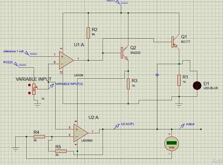
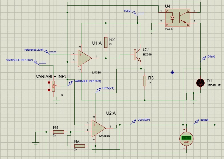
it is DC signal the source give mv and in other times give greater than 1 volt i did this circuit using comparator and npn -pnp transistors . then the output is gathered from both , absolutely one of them will give output. what do you say?


- - - Updated - - -

could i use this lm339 comparator as an amplifier instead of lm 358 opamp?
 

i found that the pnp works when the output of the comparator is zero however the input is still changed and exceeds the reference value so i replaced the pnp with optoisolator that is working when the input signal exceeds 2 volt . under 2 volt there is a small passing signal from the opto isolator .

want your comment
 

Sorry, but that circuit makes absolutely no sense to me. You've got the emitter of your transistor tied to V+, and the collector tied to VCC input of the comparator? Where's the power for the comparator? I have no idea what you've got going on there.
 

the power of the comparator is VCC , the voltage source on pin 3 as in datasheet . what is the problem? . the emitter is connected to the +ve supply of the opamp consequently when there is mv signal which is smaller than the reference , the output of the comparator will be high and that will switch on the opamp and pass the mv to be amplified, on the other hand the small signal will not switched on the optocoupler so the mv will only pass.when the signal is larger than the reference the output of the comparator will be low and that won't switch the opamp on so the larger signal will pass from the optocoupler without amplification
 
Last edited:

.............................

could i use this lm339 comparator as an amplifier instead of lm 358 opamp?
Not without added compensation. The comparator does not have the internal compensation that an opamp has to prevent oscillations in a closed loop circuit.

- - - Updated - - -

Exactly what do you want the output to look like as the input goes from 130mV to 10V?

How much do you want to amplify the 130mV signal?
 

the gain of mv signal is 2 .larger than 2 volt won't b amplified
 

You need a Gain Compressing Amplifer in other words Limiting Amplifier.Gain will be linear from DC to 500mV then it will be compressed to 1(or constant) to pass the signal beyond 500mV.If the signal audio range, you may find limiting amplifers for that purpose.
 

Below is the simulation of an amp that provides a gain of 2 up to about 2V output and then transitions to a gain of one. The one possible disadvantage to this simple circuit is that there is about a 1V offset to the output for inputs above 1V.

Vari Gain Amp.gif
 

Below is the simulation of an amp that provides a gain of 2 up to about 2V output and then transitions to a gain of one. The one possible disadvantage to this simple circuit is that there is about a 1V offset to the output for inputs above 1V.
no 1v is very big offset , what is the problem with my circuit?
 

The problem revealing with the present circuit is that a single OP with negative feedback can only generate a monotone transfer function.

Unfortunately the intended transfer function still hasn't been clearly specified. Obviously it must be nonmonotone, with a negative step in the transition between low and high input range. As a side effect, the actual input range can't be determinded only from the output voltage, you need an additional range switching logic signal.

Having said this, it should be clear that the solution must use a range comparator and an amplifier with switchable gain, preferably based on an analog switch.

To avoid further fruitless tries of yourself and misunderstandings of forum members, please start with sketching the intended transfer function.
 

The problem with any circuit that switches gain is that the input cannot be determined unambiguously from the output unless you also know when it switches the gain. Do you intend to monitor when the gain is switched?
 

The problem with any circuit that switches gain is that the input cannot be determined unambiguously from the output unless you also know when it switches the gain. Do you intend to monitor when the gain is switched?
i don't want to monitor the gain but i want to use gain in a range and other gain in different range this is just the function that i want to do.

- - - Updated - - -

To avoid further fruitless tries of yourself and misunderstandings of forum members, please start with sketching the intended transfer function.
what do you mean by sketching transfer function ? you get what i want to do.
 

Status
Not open for further replies.

Similar threads

Part and Inventory Search

Welcome to EDABoard.com

Sponsor

Back
Top