Continue to Site

Welcome to EDAboard.com

Welcome to our site! EDAboard.com is an international Electronics Discussion Forum focused on EDA software, circuits, schematics, books, theory, papers, asic, pld, 8051, DSP, Network, RF, Analog Design, PCB, Service Manuals... and a whole lot more! To participate you need to register. Registration is free. Click here to register now.

Help with 2nd order filter design

Status
Not open for further replies.

Sink0

Full Member level 6
Joined
Nov 25, 2009
Messages
390
Helped
37
Reputation
74
Reaction score
30
Trophy points
1,308
Location
Sao Paulo, Brazil
Activity points
4,186
I am working on a EMG amp project so i need to use a few filters to get a quality signal at my output. I am have been discussing with Texas Instruments about the proper way to design a second order filter when your virtual reference is at the middle of toyr supply (link to TI forum). On my design i will be using a INA333 with 3.3V supply and creating a center reference with 2 precision resistors and a voltage follower. Considering a 2nd order butterwoth MFB high-pass filter as an example. As the 1.65V reference is my filter reference it is suposed to be used the GND on a standerd bipolar supply design. But if you take a look at the filter used and posted at the Texas Instruments forum discussion it is being used the real GND at some points. They are telling me that thats the best solutions as i will need a low-impedance supply that is able to drain current. But does that really makes sense? Becouse for sure the transfer function will be different.

Any comment on that? Thank you!

Sorry if i was not clear enough!
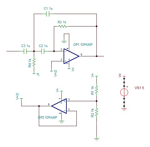
 

Sorry, matbe that can help. It is a 2nd order high pass MFB filter. As i will be using a single supply with a rail-to-rail opamp, i must create a center reference. The discussion i was having is about what should be J1 (on R4). GND or V+/2. Ideally i belive it should be v+/2 as it is my virtual reference for the filter, however a guy used GND and they told me that is better to use the GND as my virtual reference (1.65V for instance) might not be a good currtent source/sink and have a low impedance. The filter poles on both cases is the same, but not the transfer function. So what should i do? Use the virtual reference or the GND? Thank you!

99_1334376991.jpg
 

If you notice, R4 goes to three capacitors so the DC level at that point has no effect on the AC operation or transfer function of the filter (I don't understand why you think it does :???:). Thus they recommended used the actual circuit ground rather than the virtual ground, since the circuit ground has a lower AC impedance and is not affected by any frequency response limits of your virtual ground due to the characteristics of the OP2 op amp.
 
  • Like
Reactions: Sink0

    Sink0

    Points: 2
    Helpful Answer Positive Rating
Hmm thats makes sense. ANd the same is true for a low-pass filter as the capacitor would kill the DC level again. Hmm Thank you for your explanation. Howver, even with these simple explanations it is weird to think that the output would be the same. I will try to look on MFB filter math to see if that gets more clear. Thank you!
 

The math for the MTB filter transfer function includes only the AC impedances. Thus DC bias has no effect on that function. You must learn to recognize the difference between DC bias values and the AC impedance values. They often are only indirectly related.
 

Hey Sink0,

Could you say what is common mode(central voltage) of you input signal frequency. You may need to apply on V- a voltage equal to the common mode. Otherwise you will get DC voltage shift on output node. I think TI thought that input signal is bipolar(common mode is zero(GND)) and perhaps they suggest to apply GND on V- node.
I'm not entirely clear on what you are saying, but the input is AC coupled so is insensitive to any DC (common mode) on the input, and the op amp is biased at 1/2 the supply voltage so it will operate in the linear region as long as the peak-to-peak input voltage is less than the rail-to-rail output range of the op amp.
 

Could you say what is common mode(central voltage) of you input signal frequency.
It's completely meaningless, because the circuit is a high-pass. The only interesting point is the output reference voltage which is set by the virtual ground.

Two additional comments:
- OP2 is effectvely superfluous, OP1 NI input can be connected directly to the voltage divider, because it doesn't load it.
- The voltage divider should be bypassed with a capacitor to ground to suppress possible supply ripple and have the virtual ground refernced to ground AC-wise.
 
  • Like
Reactions: Sink0

    Sink0

    Points: 2
    Helpful Answer Positive Rating
Thank you for your help. But that is just simplifyed schematic i made just for this post. The full schematic is made on kikad and i got a bypass capacitor at the voltage divider and also at the output of the opamp. I am using the voltage-follower becouse the reference is available at an output so it can be further used.

About the fact the circuit is a high-pass, i was using a high pass as an example, but the question would be the same for a low-pass.

Still is weird to think that the output is the same using the virtual reference or the GND. It is not very intuitive. The capacitor argument is a killing one, but i would still have to think twice if some one placed a -10000000V at that pin. Any way i will take a look at the equations so i can mature this idea. The problem of playing too much with digital systems is that we start to lose the skill with analog circuits.

Thank you for all the help.
 

...........................

About the fact the circuit is a high-pass, i was using a high pass as an example, but the question would be the same for a low-pass.

Still is weird to think that the output is the same using the virtual reference or the GND. It is not very intuitive. The capacitor argument is a killing one, but i would still have to think twice if some one placed a -10000000V at that pin. Any way i will take a look at the equations so i can mature this idea. The problem of playing too much with digital systems is that we start to lose the skill with analog circuits.
It may be different for a low-pass filter if there is DC coupling between the input and output.

If the caps and wires are rated for 10000000V then there's no problem. :-D
 
  • Like
Reactions: Sink0

    Sink0

    Points: 2
    Helpful Answer Positive Rating
Status
Not open for further replies.

Similar threads

Part and Inventory Search

Welcome to EDABoard.com

Sponsor

Back
Top