Mywk
Newbie level 5
Hey everyone ")
What I'm trying to do: As soon as we have power, run the relay for a few seconds (adjustable by changing the Capacitor if I'm not wrong)
Note I'm not very familiar with electronics so I'm probably making a huge mistake here!
The version that works:

As soon as I click the button the LED stays on for 2 or 3 seconds.
Q: When I'm NOT pushing the button why does the multimeter shows 2V between the V+ and the Transistor Emitter?
The version that doesn't work:
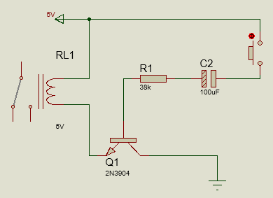
Here multimeter shows 0V between the V+ and the Transistor Emitter and when i push the button something like 0.07V
Thanks In advance, I will greatly appreciate every explanation in order to improve and learn from my mistakes
What I'm trying to do: As soon as we have power, run the relay for a few seconds (adjustable by changing the Capacitor if I'm not wrong)
Note I'm not very familiar with electronics so I'm probably making a huge mistake here!
The version that works:
As soon as I click the button the LED stays on for 2 or 3 seconds.
Q: When I'm NOT pushing the button why does the multimeter shows 2V between the V+ and the Transistor Emitter?
The version that doesn't work:
Here multimeter shows 0V between the V+ and the Transistor Emitter and when i push the button something like 0.07V
Thanks In advance, I will greatly appreciate every explanation in order to improve and learn from my mistakes
