abicash
Member level 3

Hi
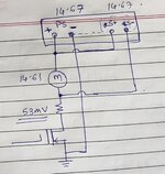
We are using a TDK GEN-60-40 Programmable Power Supply for testing few parameters for a DC motor.
As per conventional usage , the remote sensing terminals of the power supply (S+ , S-) are supposed to be connected to the actual load, so that the power supply will compensate for the cable loss.
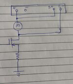
Our usage is a bit modified wherein the motor is not directly connected to Supply+ or Supply- but through a MOSFET (to turn the motor on/off) and a small shunt resistor (2 ohm) to measure the current through it.
With this scenario , there is a voltage drop in the shunt and we want to compensate this dropped voltage.
But as soon as we connect the S+, S- to Motor+, Motor- respectively , the Power supply runs in OVP (Overvoltage protection) mode.
What are we doing wrong?
Is the power supply NOT to be used in such a way?
Kindly advise.


