Continue to Site

Welcome to EDAboard.com

Welcome to our site! EDAboard.com is an international Electronics Discussion Forum focused on EDA software, circuits, schematics, books, theory, papers, asic, pld, 8051, DSP, Network, RF, Analog Design, PCB, Service Manuals... and a whole lot more! To participate you need to register. Registration is free. Click here to register now.

Help opamp getting too hot - Urgent!

Status
Not open for further replies.

gvardan

Newbie level 6
Joined
Jun 15, 2010
Messages
13
Helped
0
Reputation
0
Reaction score
0
Trophy points
1,281
Location
Canada
Activity points
1,434
Hi, or
First of all, I apologize for riposting this. Initially I posted under different category, I'm not sure how to delete or move the old post.
<- This is my original post.

Now my problem:
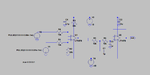
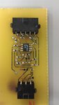
I am trying to make a circuit that would convert a pwm signal (0-5v) to a 12v to -12v analog signal. Schematic and the layout is attached. There have been several changes made to the initial circuit, and the changes are marked in the diagrams.

The circuit consists of a differential amplifier and a Sallen Key filter that suppose to get two pwm signals with complement duty cycles and output analog voltage. Dual channel LT1678 opamps are used for both Diff.amp and Sallen Key.

Issue.
We powered up the board, without any PWM inputs to the board we checked all the rails. Voltage levels are fine, but when we touched the opamp it is pretty damn hot. Also theoretically when 0V(no pwm) is given to both inputs, the output should be 0v. But we are measuring output voltage around -13.5v, this is strange.

I double checked the circuit, there's nothing wrong with soldering and no short circuits. I'm not sure what's wrong here. I have another spare opamp, but before I swap it and test, i want to double check it. Is there anything wrong with my circuit or am I missing anything, because I don't want to mess my other opamp.

I would really appreciate if someone could help me debug this.

Thanks in advance.
 

Attachments

  • Spice.png
    Spice.png
    15.5 KB · Views: 242
  • 2013-02-27 19.07.35.jpg
    2013-02-27 19.07.35.jpg
    69.7 KB · Views: 170
  • jgnt_2_mod.pdf
    40.7 KB · Views: 115
  • jgnt_2_sch_mod.pdf
    22.5 KB · Views: 100

Disconnect R5 and short C2. Tell my voltage on OUT1 and OUT2
 

Voltage levels are fine, but when we touched the opamp it is pretty damn hot. Also theoretically when 0V(no pwm) is given to both inputs, the output should be 0v. But we are measuring output voltage around -13.5v, this is strange.
Hi gvardan, this is not strange. I assume your board connections correct, sweep the positive terminal voltage from 0 to 5 volt and find the output when it becomes positive.
I think, some offset in OPAMP is affecting your circuit.
 

Check the negative power supply connection.Is it +15 or -15v?
 

Hot opamp mean high load at his output. Offset does not lead to high load.
You are telling -13V output will be loaded to supply. I wonder what combination would have been for resistance and to the supply.
Anywys, if offset is there, OPAMP will be active and it will have constant leakage from +15V to -15V, even though there is 0V input.

- - - Updated - - -

Hi gvardan,Can you check if resistance R4 is not shorted?
 

You are telling -13V output will be loaded to supply. I wonder what combination would have been for resistance and to the supply.
If there is offset, the output voltage can be-15V (in the case of rupture of feedback), but the temperature suggests that through the output stage current is flowing and the power dissipation.
 

If there is offset, the output voltage can be-15V (in the case of rupture of feedback), but the temperature suggests that through the output stage current is flowing and the power dissipation.
Yes it looks like this. IC (U1) have feedback loading when R4 get shorteda and <<R3. It will build offset of >50mV
 

R5(10K) is small load for U1
 

Thanks for all your replies, I'll go and try your suggestions today. I'm wondering whether opamp is till working condition.

I actually triple checked the board, and there are no short circuits. Also at this point the final output form the opamp is not connected to anything(load).

Here is another observation.
I removed the C1 and checked to see for any initial oscillation conditions. Interestingly, the output initially showed ~12v and then kept reducing reducing. Looked like some other cap is discharging/charging..

- - - Updated - - -

R5(10K) is small load for U1

What do you suggest the minimum value should be for R5. I'm afraid increasing R5 would increase the settling time.
 

What do you suggest the minimum value should be for R5. I'm afraid increasing R5 would increase the settling time.

I mean R5(10K) is small load for U1 to overload it.
 

The maximum supply current is 4.5mA per opamp. There are two opamps. The total supply is 30V.
Then the dissipation with no load is 4.5mA x 30V x 2= 0.27W.
The thermal resistance of the tiny surface-mount case is 190 degrees C per W so if the ambient is 30 degrees then the chip is at 81.3 degrees C which is warm but not too hot. A load makes it hotter.

Ok, now that makes sense. I was not aware of the thermal resistances stuffs. I should agree I am a noob for practical op amp designing. Thanks for sharing the knowledge.
However, I'm wondering how's this related to the ~13v output we are measuring w/o input.

Also, how do I deal with this. Should I go for a low supply current opamp or is there anyway to compensate for this on the circuit.
 

I think your opamps are defective or they are fakes.
With no input the output should be close to 0V.
 
Last edited:

The maximum supply current is 4.5mA per opamp. There are two opamps. The total supply is 30V.
Then the dissipation with no load is 4.5mA x 30V x 2= 0.27W.
The thermal resistance of the tiny surface-mount case is 190 degrees C per W so if the ambient is 30 degrees then the chip is at 81.3 degrees C which is warm but not too hot. A load makes it hotter.

81C is hot. You wouldn't normally be able to hold your finger on an IC above about 60C. However, the typical current is 2.5mA so it is likely to be cooler under normal circumstances.

Keith
 

81C is hot. You wouldn't normally be able to hold your finger on an IC above about 60C. However, the typical current is 2.5mA so it is likely to be cooler under normal circumstances.
Where can anybody buy a "typical" IC?? You get whatever they have.
Maybe somebody came before you and took all the good ones.
 

A typical IC is what you typically get! The worst case is the worst IC over the full operating temperature range. I assume he isn't working at maximum or minimum ambient temperature.

Keith
 

Where can anybody buy a "typical" IC?? You get whatever they have.
Maybe somebody came before you and took all the good ones.

I don't know, why gvardan used LT1678 op amp. Maybe because it uses LTspice.:roll: As we know is it dual rail-to-rail op amps offering both low noise and preсision. What this he needs? I know it is good op amp, but 1. supply current per amplifier max is 4.5mA, 2.Note 2: The inputs are protected by back-to-back diodes. Current limiting resistors are not used in order to achieve low noise. If differential input voltage exceeds ±1.4V, the input current should be limited to 25mA. If the common mode range exceeds either rail, the input current should be limited to 10mA, 3.Note 3: A heat sink may be required to keep the junction temperature below absolute maximum. I think, gvardan could use general purpose op amp or low power op amp, and scheme will work.
 

I agree that it is strange choice of opamp - low noise, high precision for something that could be done with a general purpose opamp at a fraction of the cost. However, I don't believe overheating is the problem. The opamp is perfectly capable of running at +/-15V without overheating provided you aren't loading the outputs too much.

Diagnosis of the problem involves measuring the actual supply current and tracing the signal through the circuit from the input to the output with the inputs connected to ground. Also, all pins of the opamp should be measured. Ideally this would be done with an oscilloscope so you can check for oscillations at each point. Breaking the connection between the two opamps (R5) may help as well.

It is possible that the chip has been fried in which case using some other cheap opamp may save some money diagnosing the problem. Also, starting with a lower supply voltage may help to find the problem before you destroy another chip.

Keith.
 

Status
Not open for further replies.

Similar threads

Part and Inventory Search

Welcome to EDABoard.com

Sponsor

Back
Top