Continue to Site

Welcome to EDAboard.com

Welcome to our site! EDAboard.com is an international Electronics Discussion Forum focused on EDA software, circuits, schematics, books, theory, papers, asic, pld, 8051, DSP, Network, RF, Analog Design, PCB, Service Manuals... and a whole lot more! To participate you need to register. Registration is free. Click here to register now.

Help me troubleshoot my QPSK modulator.

Status
Not open for further replies.

kokei74

Junior Member level 3
Joined
Apr 2, 2008
Messages
30
Helped
0
Reputation
0
Reaction score
0
Trophy points
1,286
Activity points
1,528
square-root nyquist using simulink

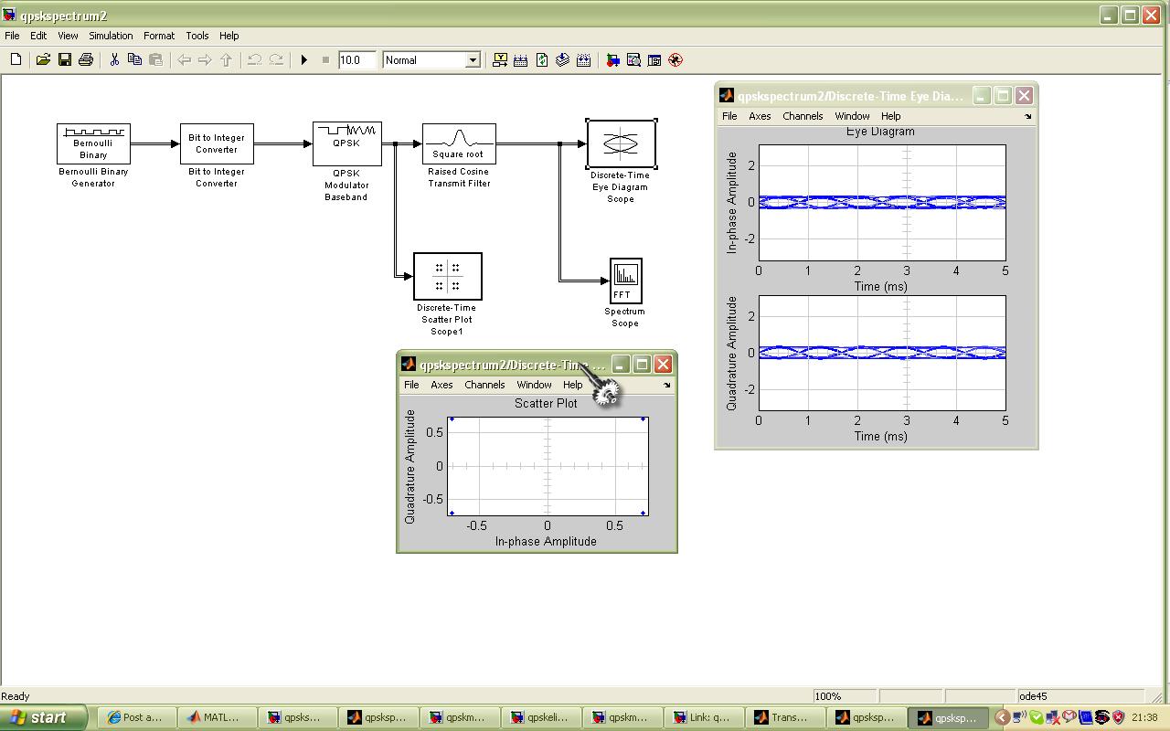
Hi, i try to implement a QPSK modulator using simulink. This is a expected result of the modulator where im using a QPSK block in library.


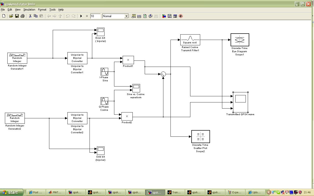
As for my own build here is the model of the QPSK block. But there is an error at Root Raised Cosine Filter block. Is im missing some parameter or others input i need to put in? If that Root Raised Cosine Filter block is not included the the eye diagram and scatter diagram is not display correctly but for the waveform its display correctly. Here is the figure of QPSK block i have create.

[/

i also have attached model files of both model. Can someone pls tell me what is the problem of my design and how to fix this?? :cry:
 

qpsk filter modulator

1.The framing method of Raised Cosine Transmit Filter should be "Maintain input frame size"(sample based);
2.Discrete-Time Scatter Plot Scope and Discrete-Time Eye Diagram Scope should be driven by a complex signal,while scope should be driven by a real type signal.
3.The Initial seeds parameter of Random-Integer Generator1 and Random-Integer Generator2 should be different from each other!Because channel I and channel Q are independent of each other.
 

    kokei74

    Points: 2
    Helpful Answer Positive Rating
bode diagram in matlab 7.7.0

GaoMing,

firstly, tq so much for ur concern...

i try to run model that u give, (qpsk_modulator_block_GM) but output can't appears because there is an error at
Root Raised Cosine filter block.i have copy the warning from matlab.


Warning: In instantiating linked block 'qpsk_modulator_block_GM/Raised Cosine Transmit Filter1'
: Raised Cosine Transmit Filter block (mask) does not have a parameter named 'framing'.
> In general\private\openmdl at 13
In open at 148
In uiopen at 196

i'm using matlab version 7.5.0...is that the reason why i got this error and influence this output?

i hope u can help me... Thanks
 

plot output signal for a qpsk modulator

kokei74 said:
GaoMing,

firstly, tq so much for ur concern...

i try to run model that u give, (qpsk_modulator_block_GM) but output can't appears because there is an error at
Root Raised Cosine filter block.i have copy the warning from matlab.


Warning: In instantiating linked block 'qpsk_modulator_block_GM/Raised Cosine Transmit Filter1'
: Raised Cosine Transmit Filter block (mask) does not have a parameter named 'framing'.
> In general\private\openmdl at 13
In open at 148
In uiopen at 196

i'm using matlab version 7.5.0...is that the reason why i got this error and influence this output?

i hope u can help me... Thanks
kokei74,
I know the reason! My matlab version is 7.7.0(R2008b).The following model file is created by matlab 7.0,you can try this :
 

using matlab to plot a qpsk modulator

owh..i see...tq GaoMing....:D

if u dont mind i would like to ask u come question. hopefuly u can help me... :)

1) what is the function of the real-imaginary to complex and complex to Real-imaginary in this operation.
2) why there is some noise at the output from scope after u put the RRC filter? i only can get a good QPSK signal if i remove the RRC filter.
3) why after we put the RRC filter, the scatter plot change being distribute?
4) what is the different between eye diagram of Q and I? or it is same between I and Q?
 

eye diagram of qpsk

pls,someone can help me....:cry:
answer this question.............:cry:
 

in generalprivateopenmdl at 13

kokei74 said:
owh..i see...tq GaoMing....:D

if u dont mind i would like to ask u come question. hopefuly u can help me... :)

1) what is the function of the real-imaginary to complex and complex to Real-imaginary in this operation.
2) why there is some noise at the output from scope after u put the RRC filter? i only can get a good QPSK signal if i remove the RRC filter.
3) why after we put the RRC filter, the scatter plot change being distribute?
4) what is the different between eye diagram of Q and I? or it is same between I and Q?
kokei74:

to your 1st question: you can see matlab help.

to your 2nd and 3rd questions: the noise is caused by intersymbol interference! do you know 1st Nyquist ISI criterion?if you know 1st Nyquist ISI criterion,the answer would be obvious,because the filter is not raised cosine filter but square root raised cosine filter ,and we know:"f(x)+g(x)=constant,for all x" does not mean that "sqrt(f(x))+sqrt(g(x))=constant,for all x".see :https://en.wikipedia.org/wiki/Nyquist_ISI_criterion

to your last question: in this model,the I and Q are the same.because I and Q are filtered by the same filter(RRC filter).
 

raised cosine qpsk

thanks GaoMing for ur clearification about this matter. From what u have post here i will try to understand and learn more in detail regarding this things. But i might need some more help from u. I hope u can help me. Thanks for ur all time helping.. : )
 

eye diagram qpsk

GaoMing;

I already read about 1st Nyquist ISI criterion..but..i still didn't understand why scatter plot change to distribute after we put the RRC filter.
i also didn't understand why the amplitude of the waveform I, Q and QPSK modulator decreasing after put the RRC filter.

i hope u can help me understand this. thanks............
 

Status
Not open for further replies.

Part and Inventory Search

Welcome to EDABoard.com

Sponsor

Back
Top