Continue to Site

Welcome to EDAboard.com

Welcome to our site! EDAboard.com is an international Electronics Discussion Forum focused on EDA software, circuits, schematics, books, theory, papers, asic, pld, 8051, DSP, Network, RF, Analog Design, PCB, Service Manuals... and a whole lot more! To participate you need to register. Registration is free. Click here to register now.

Help in designing an input dectector

Status
Not open for further replies.

coolstuff07

Advanced Member level 4
Joined
Mar 9, 2008
Messages
118
Helped
3
Reputation
6
Reaction score
1
Trophy points
1,298
Activity points
1,949
Hi,

I want to design an signal dectector whose output will be low for analog input ( sine wave) less than certain value in amplitude and high for more than certain amplitute.

For example if my reference voltage is 0.8 and my analog input signal is less than 0.3 on that reference that my circuit output should be low otherwise high.

Please help me as soon as possible.

Bye.
 

1) Your input waveform is sine only ?
2) Which frequency band has your input signal ?
3) What you mean for output high and output low ? May be logic level ?
 

Hi,

Input is sine wave
Sine wave having a frequency from 100MHz to 1GHz
The ouput of the detector is logic high or logic low based on
the amplitude of the signal.

Bye.
 

Hi,

Can any one say it can be done or not.

Bye.
 

Basically yes, but the specification is still unclear: voltage range, accuracy, switching speed.
 

Hi,

Voltage range from 0.2 to 1.2 volts. But from 0.6 to 0.8 detector output should be low and above 0.6 and above 0.8 detector output is high.

Accuracy is 1%

Switching speed is 100MHz to 1GHz.

Bye.
 

100MHz to 1 GHz high switching speed would imply a comparator that converts the sine to a square wave. I understand, that you intended a rectifier or RMS detector however.

It would have switching delay clearly above several 10 ns for a simple design. Accuracy may be improved by filtering the measurement with a higher time constant (us and above).

A simple design would be a schottky half-wave rectifier with a comparator. But amplitude response is not 1% flat without sophisticated design. Having a short PCB stub connecting the detector diode may result in several 10% of response error at 1 GHz. An impedance mateched thermal detector would be used for high accuracy requirements, but I don't expect that it's approproate here.
 

Hi,

Can you please describe circuit , which will be useful for me.

Bye
 

Hi,

No one is giving reply for my answer. Please any one help me.

Bye.
 

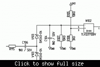
Here is a level detector circuit I used previously. The threshold voltage may be adjusted with the reference voltage divider. But the circuit possibly doesn't meet your requirements regarding flat frequency response. Alternatively, RF level measurement ICs from Analog Devices can be used with a comparator.


Hi,

Is it possible to use comparator as a signal level detector.

Bye.
 

Status
Not open for further replies.

Part and Inventory Search

Welcome to EDABoard.com

Sponsor

Back
Top