darrylcapulla
Junior Member level 1
- Joined
- Dec 15, 2014
- Messages
- 19
- Helped
- 0
- Reputation
- 0
- Reaction score
- 0
- Trophy points
- 1
- Location
- Pili, Camarines Sur, Philippines
- Activity points
- 145
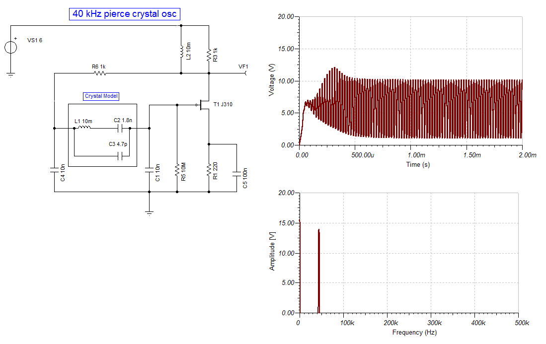
Design Pierce Oscillator to generate output frequency of 40khz.
Can anyone help me?? please
Can anyone help me?? please