Welcome to our site! EDAboard.com is an international Electronics Discussion Forum focused on EDA software, circuits, schematics, books, theory, papers, asic, pld, 8051, DSP, Network, RF, Analog Design, PCB, Service Manuals... and a whole lot more! To participate you need to register. Registration is free. Click here to register now.
If internal ADCs op mcu are used, voltage level of inputs should be converted to 0-5V range to make it compatible with ADC inpu of mcu. An amplifier stage and a full wave rectifier, built with operational amplifier can convert 'mV AC input' into DC for ADC Input from sensor.
If you are really going to practically build it then layout circuit diagram, specify components in use, get their datasheets and simulate. Heater does not necessarily require AC. it can be driven with DC.
As i said earlie, increasing 3V for every 0.1mV is not a normal way to pwer heater element without defining sensor role. Do it will cause output to switch on/off.
If for example, input is is changed from 5V to 7V, output changes from 55 to 77V. Sensor input was balanced before, now comparator tells -22 difference. Due to voltage increase, temperature starts rising. After sometime, (as heater takes time) difference narrows and then moves in +ve range. Now what you do. Switch off output, or reduce output voltage, or leave it as it is and let temperature rise without control. Note, 77V may be a bit high or low to maintain temperature required and generating a balance in comparator output. Actually sensor should control output voltage in negative feedback manner with respect to temperature setting input (0-10V) Secondly hardware will be more complicated.You have to define this 3V change/ 0.1V input in a different manner.
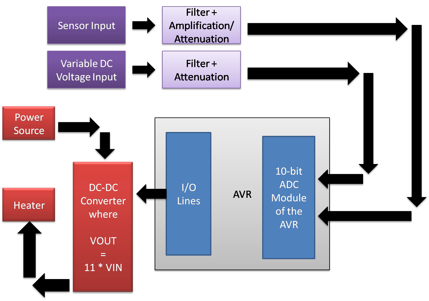
However, there is still a doubt regarding the relationship between the variable DC voltage input, the sensor input and how output voltage is going to be varied. Also, does the power to the DC-DC converter come from the variable DC input or a fixed voltage input?
This site uses cookies to help personalise content, tailor your experience and to keep you logged in if you register.
By continuing to use this site, you are consenting to our use of cookies.