chaitanya.531
Member level 1
hi folks
i getting hdl synthesis error but i get expected results
xilinx version 10.1 ise simulator
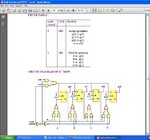
i want to write vhdl behavioral code for 7495 shift register with operation

syntax correct
but following error in synthesis
thank u
i getting hdl synthesis error but i get expected results
xilinx version 10.1 ise simulator
i want to write vhdl behavioral code for 7495 shift register with operation

syntax correct
but following error in synthesis
and by code isSynthesizing Unit <SHIFTREG>.
Related source file is "C:/Documents and Settings/chaitu/Desktop/7495beg/7495behavior/SHIFTREG.vhd".
ERROR:Xst:1534 - Sequential logic for node <q> appears to be controlled by multiple clocks.
ERROR:Xst:739 - Failed to synthesize logic for signal <q<0>>.
ERROR:Xst:1431 - Failed to synthesize unit <SHIFTREG>.
Code:
--------
library IEEE;
use IEEE.STD_LOGIC_1164.ALL;
use IEEE.STD_LOGIC_ARITH.ALL;
use IEEE.STD_LOGIC_UNSIGNED.ALL;
entity SHIFTREG is
port (
a,b,c,d: in STD_LOGIC;
si : in STD_LOGIC;
m : in STD_LOGIC;
clk0 :in STD_LOGIC;
clk1 :in STD_LOGIC;
q :inout STD_LOGIC_VECTOR (3 downto 0)
);

end SHIFTREG;

architecture Behavioral of SHIFTREG is

begin
process(clk0,clk1)
begin
if m='0' then
		if(clk0'event and clk0='0') then
			q(0)<= si;
			q(1)<=q(0);
			q(2)<=q(1);
			q(3)<=q(2);

		end if;
elsif m='1' then
		if(clk1'event and clk1='0') then
		    q(0)<=a;
			 q(1)<=b;
			 q(2)<=c;
			 q(3)<=d;

			end if;
end if;

end process;

end Behavioral;
thank u