Continue to Site

Welcome to EDAboard.com

Welcome to our site! EDAboard.com is an international Electronics Discussion Forum focused on EDA software, circuits, schematics, books, theory, papers, asic, pld, 8051, DSP, Network, RF, Analog Design, PCB, Service Manuals... and a whole lot more! To participate you need to register. Registration is free. Click here to register now.

Has anybody done this ? (AC >DC >AC converter)

Status
Not open for further replies.
I am planning to use Littlefuse PPTC Resettable fuses.
Not suited as inrush current limiter. And very few types specified for 230 V.
 
  • Like
Reactions: Okada

    Okada

    Points: 2
    Helpful Answer Positive Rating
Then which NTC can I use for AC input side and for DC at H-Bridge ? NTC are better I think because there will be no need for fuse replacement. it jsut increases its temperature and blocks the current but high voltage has to drop across the NTC.
 

Re: Has anybody done this ? (AC >DC >AC converter)

I can't and will not use bulky transformers.

This is an AC-in AC out voltage multiplier. It's capacitor-based.

It does not adapt automatically to all house voltages. It's not regulated for every load. All of this makes for unpredictable output voltage.


Notice the high volt levels. With normal house voltage the peaks rise to over 600V.

The inductors are a good idea because they smooth the waveforms through the capacitors. However the inductors are not absolutely necessary.

The transistors are necessary for the converter to operate. The bias resistors need to be adjusted carefully. They dissipate several Watts. Likewise the transistors.

The above schematic works in simulation. It's not necessarily that same one you would build. Perhaps it can be improved with more effort. For instance it would be more efficient to limit the charge on the capacitors, so that the total voltage arriving at the transistors is 330 V.

- - - Updated - - -

Surge current on power up is also a problem. It can expose the capacitors to more than 400V each.

The operation is similar to a bridge voltage doubler, with the addition of the transistors. During alternating halves of the cycle, each transistor is biased by the incoming supply, which means they convey the same waveshape as that of the incoming supply.
 
  • Like
Reactions: Okada

    Okada

    Points: 2
    Helpful Answer Positive Rating
Re: Has anybody done this ? (AC >DC >AC converter)

Please provide the falstad data.
 

Re: Has anybody done this ? (AC >DC >AC converter)

Please provide the falstad data.

Since you asked...


Code dot - [expand]
1
2
3
4
5
6
7
8
9
10
11
12
13
14
15
16
17
18
19
20
21
22
23
24
25
26
27
28
29
30
31
32
33
34
35
36
37
38
39
40
41
42
43
44
45
$ 1 1.4999999999999999E-5 4.078577355933338 36 340.0 50
d 464 368 464 256 1 0.805904783
c 464 256 320 256 0 9.999999999999999E-5 200.65586007421103
w 464 256 576 256 0
g 400 368 400 400 0
d 464 480 464 368 1 0.805904783
c 464 480 320 480 0 9.999999999999999E-5 -216.8367101555673
r 576 368 688 368 0 460.0
w 576 480 464 480 0
w 576 368 576 416 0
w 400 368 464 368 0
t 512 304 576 304 0 -1 120.22767147991942 -0.7384996724127859 100.0
w 576 256 576 288 0
w 576 320 576 368 0
t 512 432 576 432 0 1 -307.2484937908043 -0.8207627924477082 100.0
w 576 448 576 480 0
x 220 427 302 433 0 24 normal
g 688 368 688 432 0
w 464 368 512 368 0
r 512 368 512 304 0 64000.0
r 512 368 512 432 0 64000.0
O 576 368 640 400 0
x 283 220 666 226 0 24 AC-in-AC-out voltage multiplier
x 246 480 280 486 0 24 AC
x 384 294 411 299 0 20 C1
x 383 448 410 453 0 20 C2
R 256 368 256 256 0 1 50.0 255.0 0.0 -1.5707963267948966 0.5
x 234 402 290 408 0 24 sub-
x 229 454 298 460 0 24 mains
l 320 256 320 368 0 0.1 -0.6746108233287229
l 320 368 320 480 0 0.1 1.8117994189956972
w 256 368 320 368 0
O 576 256 640 256 0
O 576 480 640 480 0
x 661 268 676 274 0 24 1
x 665 491 680 497 0 24 2
x 605 347 655 353 0 24 load
o 25 32 0 34 320.0 1.6 0 -1 supply
o 25 32 0 33 234.89251465925076 4.697850293185016 0 -1 supply
o 1 32 0 35 481.63936022140547 2.4081968011070285 1 -1 C1
o 5 32 0 295 294.2755191266113 2.942755191266114 1 -1 C2
o 31 32 0 34 640.0 9.765625E-5 2 -1 out1
o 32 32 0 294 640.0 9.765625E-5 2 -1 out2
o 20 32 0 290 523.7424972633827 9.765625000000001E-155 3 -1 load
o 6 32 1 35 523.7424972633827 9.765625000000001E-155 3 -1 load


Again, this is not intended as a voltage stabilizer for all loads, or for all supply voltages.
It may not fit your needs. Notice I made the load a lowly 1/2 A. If you want it to power a refrigerator you'll need to use components that can endure the voltage, and current, and heat. I'm sure explosions are just as much a hazard with this method as with the other methods discussed.

Nevertheless it has possibilities. It's based on a simple voltage doubler, which is not that difficult to comprehend. Maybe there is a way to add regulation, and stabilization, etc. Also to increase efficiency, and reduce heat, etc.
 
  • Like
Reactions: Okada

    Okada

    Points: 2
    Helpful Answer Positive Rating
Re: Has anybody done this ? (AC >DC >AC converter)

My Rigol DS1054Z arrived. Now, I can build and test systems.
 

Attachments

  • osc scope.jpg
    osc scope.jpg
    46.5 KB · Views: 68

Re: Has anybody done this ? (AC >DC >AC converter)

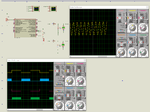
1st step is complete that is generation of full bridge SPWM signal. The signals look good on the scope.

Next and second step is designing a DC-DC Converter to get 325V VBUS voltage from 12V Battery using switching transformer.

The third step is

230V (170V - 290V) AC converted to DC and then using buck-boost converter to get constant 325V VBUS voltage. Should I use a transformer in the buck-boost converter for isolation ?

I have seen buck converters with transformer but not buck-boost converter with transformer.

Now I am getting switching transformer manufactured for second step. for a 800VA Inverter cum stabilizer.

My 10x probe measures max 300V DC.

So, I have to buy a 100x probe. Which probe is good ? It should work with my Rigol 1054Z. 50 MHz is enough for me because my Oscilloscope is 50 MHz type.


In the next step which is 12V DC to 325V DC VBUS voltage generation what care and saftey measures should be taken regarding high voltages and currents ?


There will be 4 micrcontrollers in the design.

One PIC12F1840 or PIC18F13K22 for the buck-boost converter.

second one PIC12F1840 or PIC18F13K22 for the step-up DC-DC converter

another one PIC18F26K22 for H-Bridge control

yet another one PIC18F46K22 for GLCD, fan control, etc...

Now, I also have to design PCB layout using Proteus for step-up DC-DC converter. What guidelines I have to follow in designing PCB layout for 12V to 325V DC-DC Converter ?
 

Attachments

  • DS1Z_QuickPrint1.png
    57.6 KB · Views: 72
Last edited:

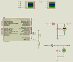
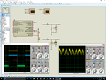
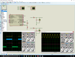
I built this filter circuit and passed the P1B and P1D SPWM signals and checked the outputs. Why the sine wave is like this ?


134433d1481597715-ds1z_quickprint2.png


Edit: Updated Image attached. It shows frequency of sinewave as 40 Hz ? Why ? mikroC PRO PIC project is attached. Calculations inside the ISR.

I have to get 50 Hz Sinewave.


Code C - [expand]
1
2
3
4
5
6
7
8
9
10
11
12
13
14
15
16
17
18
19
20
21
22
23
24
25
26
27
28
29
30
31
32
33
34
35
36
37
38
39
40
41
42
43
44
45
46
47
48
49
50
51
52
53
54
55
56
57
58
59
60
61
62
63
64
65
66
67
68
69
70
71
72
73
74
75
76
77
78
79
80
81
82
83
84
85
86
87
88
89
90
91
92
93
94
95
96
97
98
99
100
101
102
103
104
105
106
107
108
109
110
111
112
113
114
115
116
117
118
119
120
121
122
123
124
125
126
127
128
129
130
131
132
133
134
135
136
137
138
139
140
141
142
143
144
145
146
147
148
149
150
151
152
153
154
155
156
157
158
159
160
161
162
163
164
165
166
167
168
169
170
171
172
173
174
175
176
177
178
179
180
181
182
183
184
185
186
187
188
189
190
191
192
193
194
195
// LCD module connections
sbit LCD_RS at LATC0_bit;
sbit LCD_EN at LATC3_bit;
sbit LCD_D4 at LATC4_bit;
sbit LCD_D5 at LATC5_bit;
sbit LCD_D6 at LATC6_bit;
sbit LCD_D7 at LATC7_bit;
 
sbit LCD_RS_Direction at TRISC0_bit;
sbit LCD_EN_Direction at TRISC3_bit;
sbit LCD_D4_Direction at TRISC4_bit;
sbit LCD_D5_Direction at TRISC5_bit;
sbit LCD_D6_Direction at TRISC6_bit;
sbit LCD_D7_Direction at TRISC7_bit;
// End LCD module connections
 
char msg[17];
 
const char msg1[] = "    Inverter    ";
const char msg2[] = "";
const char msg3[] = "";
const char msg4[] = "";
 
#define DEMO_LIMIT_MAX 3
#define DEMO_LIMIT_MAX_ADDRESS 0x10
 
char demo_limit = 0;
 
const unsigned char sine_table[64] = {
    0,1,2,5,10,15,21,29,
    37,47,57,67,79,90,103,115,
    128,140,152,165,176,188,198,208,
    218,226,234,240,245,250,253,254,
    255,254,253,250,245,240,234,226,
    218,208,198,188,176,165,152,140,
    128,115,103,90,79,67,57,47,
    37,29,21,15,10,5,2,1    
};
 
/*
const unsigned int sine_table[64] = {
    512,562,611,660,707,753,796,836,
    873,907,937,963,984,1001,1013,1021,
    1023,1021,1013,1001,984,963,937,907,
    873,836,796,753,707,660,611,562,
    512,461,412,363,316,270,227,187,
    150,116,86,60,39,22,10,2,
    0,2,10,22,39,60,86,116,
    150,187,227,270,316,363,412,461
};
*/
 
unsigned int TBL_POINTER_NEW = 0, TBL_POINTER_OLD = 0, TBL_POINTER_SHIFT = 0, DUTY_CYCLE = 0, SET_FREQ = 512;
 
//Timer2
//Prescaler 1:1; Postscaler 1:2; TMR2 Preload = 194; Actual Interrupt Time : 78 us (because 12.820 KHz PWM)
//Place/Copy this part in declaration section
void InitTimer2() {
    T2CON = 0x0C;
    TMR2IE_bit = 1;
    PR2 = 194;
    INTCON = 0xC0;
}
 
void interrupt() {     
     if(TMR2IF_bit) { 
        //Enter your code here
        
        //SET_FREQ = 65536 / (64 * 2) = 512
        //Required AC Frequency = 50 Hz
        //PWM Freq = 12821 Hz
        //Tpwm = 1/12.821 KHz = 78 us  (Timer2 Interrupt Period)
        //78 us * 64 * 2 = 9984 = 9.984 ms (for 180 degrees)
        //9.984 * 2 = 19.968 ms
        //AC freq = 1/19.968 ms = 50.08 Hz      
              
        TBL_POINTER_NEW = TBL_POINTER_OLD + SET_FREQ;
        
        if(TBL_POINTER_NEW < TBL_POINTER_OLD) {
           CCP1CON.P1M1 = ~CCP1CON.P1M1;      //Reverse direction of full-bridge           
        }
        
        TBL_POINTER_SHIFT = TBL_POINTER_NEW >> 10;
        DUTY_CYCLE = TBL_POINTER_SHIFT;               
        
        //Assign PWM duty 10 bit        
        CCPR1L = (sine_table[DUTY_CYCLE] & 0x3FC) >> 2;
        CCP1CON.DC1B1 = (sine_table[DUTY_CYCLE] & 0x02) >> 1;
        CCP1CON.DC1B0 = (sine_table[DUTY_CYCLE] & 0x01);       
                       
        TBL_POINTER_OLD = TBL_POINTER_NEW; 
        
        TMR2IF_bit = 0;        
     }    
}
 
char *CopyConst2Ram(char *dest, const code char *src) {
    char *d;
 
    d = dest;
    
    for(;*dest++ = *src++;)asm clrwdt;
 
    return d;
}
 
void main() {
     asm clrwdt
     
     /*
     demo_limit = EEPROM_Read(DEMO_LIMIT_MAX_ADDRESS);
     Delay_ms(20);
     
     if(demo_limit <= DEMO_LIMIT_MAX) {
        demo_limit++;
        EEPROM_Write(DEMO_LIMIT_MAX_ADDRESS, demo_limit);
        Delay_ms(20);
     }
     */
     
     //if(demo_limit < DEMO_LIMIT_MAX) {
         CM1CON0 = 0x00;
         CM2CON0 = 0x00;
 
         SLRCON = 0x00;
 
         ANSELA = 0x00;
         ANSELB = 0x00;
         ANSELC = 0x00;
         ANSELD = 0x00;
         ANSELE = 0x00;
 
         TRISA = 0xC7;
         TRISB = 0b00010110;
         TRISC = 0b00000110;
         TRISD = 0x00;
         TRISE = 0x00;
 
         PORTA = 0x00;
         PORTB = 0x00;
         PORTC = 0x00;
         PORTD = 0x00;
         PORTE = 0x00;
 
         LATA = 0x00;
         LATB = 0x00;
         LATC = 0x00;
         LATD = 0x00;
         LATE = 0x00;
         
         //PWM1_Init(30000);      //DC-DC Converter
         //PWM1_Set_Duty(250);
         //PWM1_Stop();
         //PWM1_Start();
         
         //PWM4_Init(12821);
         //PWM4_Set_Duty(127);      //FAN
         //PWM4_Stop();
         //PWM4_Start();
 
         PWM3_Init(12821);
         PWM3_Set_Duty(0);
 
         CCP1CON.CCP1M3 = 1;
         CCP1CON.CCP1M2 = 1;
         CCP1CON.CCP1M1 = 0;
         CCP1CON.CCP1M0 = 0;
 
         CCP1CON.P1M0 = 1;
         CCP1CON.P1M1 = 0;
 
         InitTimer2();
 
         TRISB = 0x00;
         TRISC = 0x00;
 
         Delay_ms(200);
         /*
         LCD_init();
         LCD_Cmd(_LCD_CURSOR_OFF);
         LCD_Cmd(_LCD_CLEAR);
         
         LCD_Out(1,1,CopyConst2Ram(msg, msg1));
         */
         
         PWM3_Start();
     //}
                  
     while(1) {     
          asm clrwdt
          if(demo_limit < DEMO_LIMIT_MAX) {
          
          }
     }
}


Attachments

  • DS1Z_QuickPrint2.png
    51.4 KB · Views: 132
  • SW.png
    SW.png
    54.3 KB · Views: 70
  • Pure Sinewave Stabilizer Cum Inverter.rar
    42 KB · Views: 71
  • DS1Z_QuickPrint4.png
    DS1Z_QuickPrint4.png
    51.8 KB · Views: 66
Last edited:

Re: Has anybody done this ? (AC &gt;DC &gt;AC converter)

Actually first I calculated the values 320E and 10uF for the RC filter (50 Hz cut-off frequency) but later I read on the net that I have to use Ceramic Capacitor. So, for Arduino PWM it was mentioned to use 3.9k and 100nF and I used it.

Should I use 32K and 100nF ?

R = 1/2*3.1415*50*100n = 32k

If I use 32k in Proteus then I am getting proper signal but if I use 3.9k then signal is distorted same as in real hardware.

What is the reason for signal distortion ?

Finally, I am building 800W Stabilizer Cum Inverter as first power electronics project. If I succeed then I will build 5KW Stabilizer Cum Inverter.

Here are my calculations.

V = 230V, P = 800W

I = 800W/230V = 3.48A

Ipk = 3.48 * 1.4142 = 4.92 = ~ 5A

Rds(on) = 0.110E (IRFPS40N60KPBF)

Pd/mosfet = I^2R = 5*5*0.110 = 2.75W

Total Pd is 2.75 * 2 = 5.5W


Should I consider current more than 5A ?

- - - Updated - - -

Edit 2:

Ok. I changed the resistor to 32k. Now the signal is correct. Now I can feed it to Mosfets using FET drivers.

See scope image.

Please explain why signal was distorted.

134439d1481609171-ds1z_quickprint5.png
 

Attachments

  • filter #1.png
    filter #1.png
    276.6 KB · Views: 65
  • filter #2.png
    filter #2.png
    274.8 KB · Views: 70
  • DS1Z_QuickPrint5.png
    45.4 KB · Views: 120

Re: Has anybody done this ? (AC &gt;DC &gt;AC converter)

Ok. I changed the resistor to 32k. Now the signal is correct. Now I can feed it to Mosfets using FET drivers.

May be I am confusing. Will you feed this sinewave signal to MOSFET using FET Driver?
 

Re: Has anybody done this ? (AC &gt;DC &gt;AC converter)

May be I am confusing. Will you feed this sinewave signal to MOSFET using FET Driver?
He just can't decide what to develop - voltage inverter or audio amplifier )))
 

Re: Has anybody done this ? (AC &gt;DC &gt;AC converter)

No, I am not going to feed Sinewave to FET Driver or Mosfet. I just wanted to see if SPWM signal really gives proper sine wave after filtering. In actual hardware SPWM signal (without filter) is fed to FET drivers IR2184s and FET drivers will drive the 4 Mosfets of the Full-Bridge. Finally a Butterworth filter will be put at the output of Mosfet Bridge.

Got the 50 Hz output. I had by mistake calculated Timer2 Interrupt period for a different Clock Frequency.

This is the new changed code.

Code:
//Timer2
//Prescaler 1:1; Postscaler 1:1; TMR2 Preload = 155; Actual Interrupt Time : 78 us
//Place/Copy this part in declaration section
void InitTimer2() {
    T2CON = 0x04;
    TMR2IE_bit = 1;
    PR2 = 155;
    INTCON = 0xC0;
}


Now, Sinewave is 50 Hz.
 

Attachments

  • DS1Z_QuickPrint6.png
    DS1Z_QuickPrint6.png
    43.8 KB · Views: 65
  • Pure Sinewave Stabilizer Cum Inverter Simulation.rar
    55 KB · Views: 63
Last edited:

Re: Has anybody done this ? (AC &gt;DC &gt;AC converter)

I am planning to make a AC to DC and DC to AC that is AC-DC-AC constant voltage stabilizer for refrigirator.

If the main aim to design constant voltage stabiliser, you may approach the concept of static voltage stabiliser which is expected to fast response to any change in voltage, have fairly constant output. See the block diagram.
 

Attachments

  • static-stab-principle.jpg
    static-stab-principle.jpg
    68 KB · Views: 71

Re: Has anybody done this ? (AC &gt;DC &gt;AC converter)

I have checked some articles about static voltage stabilizers and also have EFY project with code of a static voltage stabilizer but they use bulky transformers. I don't want transformer based. I will design a buck-boost converter for getting the 325V constant VBUS voltage. Now before designing the AC-DC buck-boost converter I have two issues.

1. I need to complete the Full-Bridge Driver board layout and for that I need to design a output filter.
2. I need a method preferably TTL for inter board communication because I have 5 PICs and 5 boards in the project because one PIC can't generate different frequency PWMs and I want different frequency PWMs for each module.

One MCU for SMPS Battery Charger
One MCU for 12V to 325V DC-DC Converter
One MCU for 170V-290V AC to 325V DC AC-DC Converter
One MCU for Full-Bridge Driver
One MCU for Driving LCD


First I need to solve these two issues. After that I will design AC-DC Buck-Boost Converter.
 

Re: Has anybody done this ? (AC &amp;gt;DC &amp;gt;AC converter)

Edit:

After lot of searching I found this very good mosfet.

Now

Pd(mosfet) is 5*5*0.036 = 0.9W

Total power dissipation in Full-Bridge is 0.9 * 2= 1.8W

The Mosfet is high priced but good for my application.

- - - Updated - - -

I read this and saw th eanimation of the buck-boost converter.

https://www.learnabout-electronics.org/PSU/psu33.php

If I need to design a synchronous Buck-Boost Converter do I need 4 Mosfets ?
 

Attachments

  • IXKK85N60C.pdf
    212.2 KB · Views: 64

I just have some doubts regarding precautions to be taken like

What happens if terminals of a 12V 200Ah battery are shorted ? Will the battery explode ?

If I use a 230V AC to 14.4V DC buck converter for battery charging then what happens if PWM duty is 100% or if mosfet shorts. Will the 325V DC appear across the battery terminal and explode the battery ?

Oh yes, it will spray a HOT cloud of sulfuric acid.
I've seen it once from a safe distance. The adjacent brick wall started to fizzle. Everyone in the building had to be evacuated immediately, as it felt like a fork had been pitched thru your nose.
I cannot imagine the type of burns someone would have suffered if he had been close.
 

I found a way to increase AC voltage by 30-50 percent, yet without the massive wasteful resistive drop as in my post #23. Charge capacitors in series during one-half of the cycle. Then discharge them in parallel, while adding supply voltage. The result is to multiply mains AC by as much as 1.5.


The transistors automatically turn On and Off at correct times in the cycle.
The job could be done by simple switches (if such a component existed). Thus it is not the transistors' function so much to drop a higher voltage to a lower voltage through a resistance. (This topology is more efficient than my post #23.)

If desired, the bias can be adjusted to cause the transistors to provide some amount of resistive drop. Therefore this can be a means to match unpredictable house voltage to unpredictable loads. To make the adjustment automatic will require more design work, of course.

I believe this idea has possibilities. Perhaps it can be my million dollar idea? (I've been looking for a million dollar idea.) Is there an American market for a mains voltage booster? Unfortunately my idea would be a quick way to destroy appliances, as long as our house voltage is healthy, that is.
 
  • Like
Reactions: Okada

    Okada

    Points: 2
    Helpful Answer Positive Rating
I am referring these

https://tahmidmc.blogspot.in/2013/02/demystifying-use-of-table-pointer-in.html

https://tahmidmc.blogspot.in/2012/11/feedback-in-sine-wave-inverter-pic16f.html

Below is my latest code of Full-Bridge Driver.

Working explained in the code (in comments)

I have changed the Oscillator to 4 MHz Internal.

PIC is PIC18F46K22, OSCCON and OSCTUNE configurations are correct but I am getting 30 Hz Sinewave. Why ?

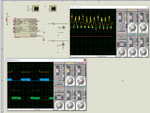
Also there is another problem. if feedback value is >= 512 then I am getting sinewave but if feedback value is less than 512 I am getting distorted signal and also frequency is 50 Hz. What is the problem ?

Also same problem in Proteus. I guess problem is with code.

I have attached mikroC PRO PIC project, Proteus Simulation file.

Edit:

Here is the code.


Code C - [expand]
1
2
3
4
5
6
7
8
9
10
11
12
13
14
15
16
17
18
19
20
21
22
23
24
25
26
27
28
29
30
31
32
33
34
35
36
37
38
39
40
41
42
43
44
45
46
47
48
49
50
51
52
53
54
55
56
57
58
59
60
61
62
63
64
65
66
67
68
69
70
71
72
73
74
75
76
77
78
79
80
81
82
83
84
85
86
87
88
89
90
91
92
93
94
95
96
97
98
99
100
101
102
103
104
105
106
107
108
109
110
111
112
113
114
115
116
117
118
119
120
121
122
123
124
125
126
127
128
129
130
131
132
133
134
135
136
137
138
139
140
141
142
143
144
145
146
147
148
149
150
151
152
153
154
155
156
157
158
159
160
161
162
163
164
165
166
167
168
169
170
171
172
173
174
175
176
177
178
179
180
181
182
183
184
185
186
187
188
189
190
191
192
193
194
195
196
197
198
199
200
201
202
203
204
205
206
207
208
209
210
211
212
213
214
215
216
217
218
219
220
221
222
223
224
225
226
227
228
229
230
231
232
233
234
235
236
237
238
239
240
241
242
243
244
245
246
247
248
249
250
251
252
253
254
255
256
257
258
259
260
261
262
263
264
265
266
267
268
269
270
271
272
273
274
275
276
277
278
279
280
281
282
283
284
285
286
287
288
289
290
291
292
293
294
295
296
297
298
299
300
301
302
303
304
305
306
307
308
309
310
311
312
313
314
315
316
317
318
319
320
321
322
323
324
325
326
327
328
329
330
331
332
333
334
335
336
337
338
339
340
341
342
343
344
345
346
347
348
349
350
351
352
353
354
355
356
357
358
359
360
361
362
363
364
365
366
367
368
369
370
371
372
373
374
375
// LCD module connections
sbit LCD_RS at LATB4_bit;
sbit LCD_EN at LATB5_bit;
sbit LCD_D4 at LATB0_bit;
sbit LCD_D5 at LATB1_bit;
sbit LCD_D6 at LATB2_bit;
sbit LCD_D7 at LATB3_bit;
 
sbit LCD_RS_Direction at TRISB4_bit;
sbit LCD_EN_Direction at TRISB5_bit;
sbit LCD_D4_Direction at TRISB0_bit;
sbit LCD_D5_Direction at TRISB1_bit;
sbit LCD_D6_Direction at TRISB2_bit;
sbit LCD_D7_Direction at TRISB3_bit;
// End LCD module connections
 
#define MAX_DEMO_LIMIT 20
#define MAX_DEMO_LIMIT_ADDRESS 0x20
 
#define FBCh 0
 
char demo_limit = 0;
char msg[17];
unsigned int FBV = 0, FB_Step = 0, adder = 0;
 
const char msg1[] = "   Stabilizer   ";
const char msg2[] = "    Inverter    ";
const char msg3[] = "";
const char msg4[] = "";
 
const unsigned char sine_table[960] = {
    0,0,2,4,6,10,14,18,
    24,30,36,43,50,58,66,74,
    82,89,97,105,113,120,127,133,
    139,145,149,153,157,159,161,163,
    163,163,161,159,157,153,149,145,
    139,133,127,120,113,105,97,89,
    82,74,66,58,50,43,36,30,
    24,18,14,10,6,4,2,0,
    
    0,0,2,4,6,10,14,19,
    25,31,38,45,52,60,68,76,
    85,93,101,109,117,124,131,138,
    144,150,155,159,163,165,167,169,
    169,169,167,165,163,159,155,150,
    144,138,131,124,117,109,101,93,
    85,76,68,60,52,45,38,31,
    25,19,14,10,6,4,2,0,    
 
    0,0,2,4,7,10,15,20,
    26,32,39,46,54,62,70,79,
    88,96,105,113,121,129,136,143,
    149,155,160,165,168,171,173,175,
    175,175,173,171,168,165,160,155,
    149,143,136,129,121,113,105,96,
    88,79,70,62,54,46,39,32,
    26,20,15,10,7,4,2,0,
    
    0,0,2,4,7,11,15,21,
    27,33,40,48,56,64,73,82,
    91,99,108,117,125,133,141,148,
    154,160,166,170,174,177,179,181,
    181,181,179,177,174,170,166,160,
    154,148,141,133,125,117,108,99,
    91,82,73,64,56,48,40,33,
    27,21,15,11,7,4,2,0,
    
    0,0,2,4,7,11,16,21,
    28,34,42,50,58,67,76,85,
    94,103,112,121,130,138,146,154,
    160,167,172,177,181,184,186,188,
    188,188,186,184,181,177,172,167,
    160,154,146,138,130,121,112,103,
    94,85,76,67,58,50,42,34,
    28,21,16,11,7,4,2,0,
    
    0,0,2,4,7,11,16,22,
    28,35,43,51,60,69,78,87,
    97,107,116,125,134,143,151,159,
    166,172,178,183,187,190,192,194,
    194,194,192,190,187,183,178,172,
    166,159,151,143,134,125,116,107,
    97,87,78,69,60,51,43,35,
    28,22,16,11,7,4,2,0,
    
    0,0,2,4,8,12,17,23,
    29,37,44,53,62,71,80,90,
    100,110,120,129,138,147,156,163,
    171,177,183,188,192,196,198,200,
    200,200,198,196,192,188,183,177,
    171,163,156,147,138,129,120,110,
    100,90,80,71,62,53,44,37,
    29,23,17,12,8,4,2,0,
    
    0,0,2,4,8,12,17,23,
    30,38,46,54,64,73,83,93,
    103,113,123,133,142,152,160,168,
    176,183,189,194,198,202,204,206,
    206,206,204,202,198,194,189,183,
    176,168,160,152,142,133,123,113,
    103,93,83,73,64,54,46,38,
    30,23,17,12,8,4,2,0,
    
    0,1,2,5,8,13,18,24,
    31,39,47,56,66,76,86,96,
    107,117,127,137,147,157,166,174,
    182,189,195,200,205,208,211,212,
    213,212,211,208,205,200,195,189,
    182,174,166,157,147,137,127,117,
    107,96,86,76,66,56,47,39,
    31,24,18,13,8,5,2,1,
    
    0,1,2,5,8,13,18,25,
    32,40,49,58,68,78,88,99,
    110,120,131,141,151,161,170,179,
    187,194,201,206,211,214,217,218,
    219,218,217,214,211,206,201,194,
    187,179,170,161,151,141,131,120,
    110,99,88,78,68,58,49,40,
    32,25,18,13,8,5,2,1,
    
    0,1,2,5,9,13,19,26,
    33,41,50,59,69,80,91,101,
    113,124,134,145,156,166,175,184,
    192,199,206,212,216,220,223,224,
    225,224,223,220,216,212,206,199,
    192,184,175,166,156,145,134,124,
    113,101,91,80,69,59,50,41,
    33,26,19,13,9,5,2,1,
    
    0,1,2,5,9,14,19,26,
    34,42,51,61,71,82,93,104,
    116,127,138,149,160,170,180,189,
    197,205,212,217,222,226,229,230,
    231,230,229,226,222,217,212,205,
    197,189,180,170,160,149,138,127,
    116,104,93,82,71,61,51,42,
    34,26,19,14,9,5,2,1,
    
    0,1,2,5,9,14,20,27,
    35,44,53,63,73,84,96,107,
    119,131,142,154,165,175,185,194,
    203,211,218,224,229,233,236,237,
    238,237,236,233,229,224,218,211,
    203,194,185,175,165,154,142,131,
    119,107,96,84,73,63,53,44,
    35,27,20,14,9,5,2,1,
    
    0,1,2,5,9,14,21,28,
    36,45,54,64,75,87,98,110,
    122,134,146,157,169,180,190,199,
    208,216,223,230,235,239,242,243,
    244,243,242,239,235,230,223,216,
    208,199,190,180,169,157,146,134,
    122,110,98,87,75,64,54,45,
    36,28,21,14,9,5,2,1,
    
    0,1,2,5,10,15,21,28,
    37,46,56,66,77,89,101,113,
    125,137,149,161,173,184,194,204,
    213,222,229,235,240,245,248,249,
    250,249,248,245,240,235,229,222,
    213,204,194,184,173,161,149,137,
    125,113,101,89,77,66,56,46,
    37,28,21,15,10,5,2,1            
};
 
unsigned int TBL_POINTER_NEW = 0, TBL_POINTER_OLD = 0, TBL_POINTER_SHIFT = 0, DUTY_CYCLE = 0, SET_FREQ = 512;
 
//Timer2
//Prescaler 1:1; Postscaler 1:1; TMR2 Preload = 77; Actual Interrupt Time : 78 us @ 4 MHz Internal Oscillator
//Place/Copy this part in declaration section
void InitTimer2() {
    T2CON = 0x04;
    TMR2IE_bit = 1;
    PR2 = 77;
    INTCON = 0xC0;
}
 
void interrupt() {     
     if((TMR2IE_bit) && (TMR2IF_bit)) { 
        //Enter your code here
        
        //SET_FREQ = 65536 / (64 * 2) = 512
        //Required AC Frequency = 50 Hz
        //PWM Freq = 12821 Hz
        //Tpwm = 1/12.821 KHz = 78 us  (Timer2 Interrupt Period)
        //78 us * 64 * 2 = 9984 = 9.984 ms (for 180 degrees)
        //9.984 * 2 = 19.968 ms
        //AC freq = 1/19.968 ms = 50.08 Hz      
              
        TBL_POINTER_NEW = TBL_POINTER_OLD + SET_FREQ;
        
        if(TBL_POINTER_NEW < TBL_POINTER_OLD) {
           CCP1CON.P1M1 = ~CCP1CON.P1M1;      //Reverse direction of full-bridge           
        }
        
        TBL_POINTER_SHIFT = TBL_POINTER_NEW >> 10;
        DUTY_CYCLE = TBL_POINTER_SHIFT + adder;               
        
        //Assign PWM duty 10 bit        
        CCPR1L = (sine_table[DUTY_CYCLE] & 0x3FC) >> 2;
        CCP1CON.DC1B1 = (sine_table[DUTY_CYCLE] & 0x02) >> 1;
        CCP1CON.DC1B0 = (sine_table[DUTY_CYCLE] & 0x01);       
                       
        TBL_POINTER_OLD = TBL_POINTER_NEW; 
        
        TMR2IF_bit = 0;        
     }    
}
 
char *CopyConst2Ram(char *dest, const code char *src) {
    char *d;
 
    d = dest;
    
    for(;*dest++ = *src++;)asm clrwdt;
 
    return d;
}
 
void main() {
     
     asm clrwdt
     
     OSCCON = 0x57;
     OSCTUNE = 0x00;
          
     /*
     demo_limit = EEPROM_Read(MAX_DEMO_LIMIT_ADDRESS);
     Delay_ms(20);
     
     if(demo_limit <= MAX_DEMO_LIMIT) {
        demo_limit++;
        EEPROM_Write(MAX_DEMO_LIMIT_ADDRESS, demo_limit);
        Delay_ms(20);
     }
     */
          
     CM1CON0 = 0x00;
     CM2CON0 = 0x00;
 
     SLRCON = 0x00;
 
     ADCON1 = 0x80;
     ADCON2 = 0b10110101;
     
     ANSELA = 0x01;
     ANSELB = 0x00;
     ANSELC = 0x00;
     ANSELD = 0x00;
     ANSELE = 0x00;
               
     TRISA = 0xC1;
     TRISB = 0x00;
     TRISC = 0x06;
     TRISD = 0xE0;
     TRISE = 0x00;
 
     PORTA = 0x00;
     PORTB = 0x00;
     PORTC = 0x00;
     PORTD = 0x00;
     PORTE = 0x00;
 
     LATA = 0x00;
     LATB = 0x00;
     LATC = 0x00;
     LATD = 0x00;
     LATE = 0x00;
          
     //PWM4_Init(12821);
     //PWM4_Set_Duty(127);      //FAN
     //PWM4_Stop();
     //PWM4_Start();
 
     PWM3_Init(12821);
     PWM3_Set_Duty(0);
 
     CCP1CON.CCP1M3 = 1;
     CCP1CON.CCP1M2 = 1;
     CCP1CON.CCP1M1 = 0;
     CCP1CON.CCP1M0 = 0;
              
     CCP1CON.P1M0 = 1;
     CCP1CON.P1M1 = 0;
     
     Delay_ms(200);
     
     // Lcd code doesn't work if called after InitTimer2()
     // as ISR will be called every 78 us
          
     LCD_Init();                        
     LCD_Cmd(_LCD_CURSOR_OFF);
     LCD_Cmd(_LCD_CLEAR);
          
     LCD_Out(1,1,CopyConst2Ram(msg, msg1));
     
     InitTimer2();
         
     TRISC = 0x00;
     TRISD = 0x00;
        
     PWM3_Start();
                       
     while(1) {     
          
          asm clrwdt
          
          //if(demo_limit < MAX_DEMO_LIMIT) {
          
          //}
          
          FBV = ADC_Read(FBCh);
          
          if(FBV < 512) {
             if(++FB_Step > 14) {     // eg: 14 = (0 to 14) no. of pwm duty sets in the array
                FB_Step = 14;         // example if FB_Step = 15 then (see last line)
             }
          }
          else{
               if(FB_Step > 0) {
                  FB_Step--;
               }
          }
          
          adder = FB_Step << 6;      // << 6 because I have 2^6 = 64 entries in each pwm duty set
                                     // 14 << 6 =  896
                                     
                                     /* ********** code from ISR ***********
                                     TBL_POINTER_NEW = TBL_POINTER_OLD + SET_FREQ;
        
                                     if(TBL_POINTER_NEW < TBL_POINTER_OLD) {
                                     CCP1CON.P1M1 = ~CCP1CON.P1M1;      //Reverse direction of full-bridge           
                                     }
        
                                     TBL_POINTER_SHIFT = TBL_POINTER_NEW >> 10;
                                     DUTY_CYCLE = TBL_POINTER_SHIFT + adder;
                                     
                                     /* *************************************
                                     
                                     Eg: TBL_POINTER_NEW = TBL_POINTER_OLD + SET_FREQ;
                                     
                                         TBL_POINTER_NEW = 0 + 512;   //512
                                     
                                         TBL_POINTER_SHIFT = 512 >> 10; // 0
                                         
                                         DUTY_CYCLE = TBL_POINTER_SHIFT + adder;  //adder = 896, FB_Step = 14
                                         
                                         DUTY_CYCLE = 0 + 896;
                                         
                                     // In the 64 pwm duties (of each pwm duty set), each duty is called twice
                                     // to get 50 Hz
                                     
                                     TBL_POINTER_NEW = TBL_POINTER_OLD + SET_FREQ;
                                     
                                     // So, (SET_FREQ * 64 * 2) = 512 * 64 * 2 = 65536
                                     
                                     //So,
                                     
                                     Eg: TBL_POINTER_NEW = TBL_POINTER_OLD + SET_FREQ;
                                     
                                         TBL_POINTER_NEW = (65536 - 512) + 512;   //65536
                                     
                                         TBL_POINTER_SHIFT = 65536 >> 10; // 64
                                         
                                         DUTY_CYCLE = TBL_POINTER_SHIFT + adder;  //adder = 896, FB_Step = 14 
                                         
                                         DUTY_CYCLE = 64 + 896; //960 (last entry of the array that is 1) 
                                         
                                     */
                                           
                                      
     }
}


Attachments

  • distorted signal.png
    distorted signal.png
    204.7 KB · Views: 57
  • DS1Z_QuickPrint7.png
    DS1Z_QuickPrint7.png
    47.2 KB · Views: 65
  • DS1Z_QuickPrint8.png
    48.4 KB · Views: 67
  • Pure Sinewave Stabilizer Cum Inverter #1.rar
    86.3 KB · Views: 62
  • sinewave.png
    sinewave.png
    202.6 KB · Views: 61
Last edited:

Also there is another problem. if feedback value is >= 512 then I am getting sinewave but if feedback value is less than 512 I am getting distorted signal and also frequency is 50 Hz

There was a mistake.

Also there is another problem. if feedback value is >= 512 then I am getting sinewave but if feedback value is less than 512 I am getting distorted signal and also frequency is not 50 Hz
 

PIC is PIC18F46K22, OSCCON and OSCTUNE configurations are correct but I am getting 30 Hz Sinewave. Why ?

Guess your verbose interrupt code doesn't execute in 78 us. Besides cleaning it up, you could run the CPU with faster clock.
 

Status
Not open for further replies.

Similar threads

Part and Inventory Search

Welcome to EDABoard.com

Sponsor

Back
Top