Vermes
Advanced Member level 4
It is a project of a universal GSM driver based on a well known and popular GSM module from SIMCom – SIM900. With this project, you can get familiar with possibilities of SIM900 module and its control via AT commands.
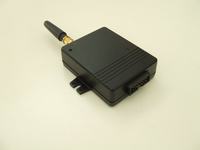
Pictures:


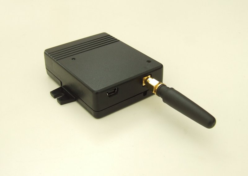


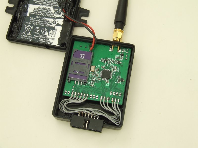
Construction:

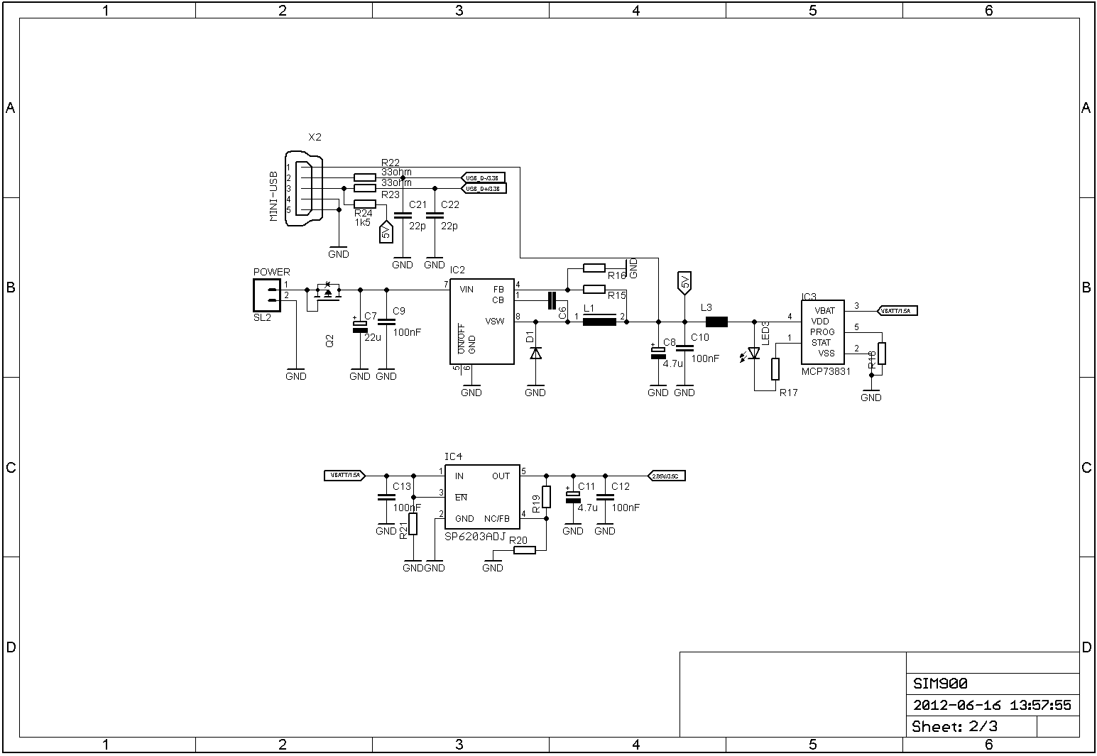

The main element of the system is microcontroller with core (Cortex-M3 from ST: STM32F103C8T6) in 48 pins housing. The whole circuit was mounted on a two-sided PCB with dimensions of 5x5cm and closed in housing KM-21. That size of the PCB was due to the fact, that the prototype should be as cheap as possible. The system is powered from a battery (Nokia BP-4L 1500mAh/3,6V). You can also power by a mini-USB socket, or from an external power supply (5-24V). MCP73831 is responsible for charging Li-Po batteries. SIM900D module has a built in system for charging accumulators, but its size is bigger than SIM900 (33x33mm and 24x24mm). Application schematic is a standard construction of the manufacturer. Due to the maximum voltage on lines RxD/TxD of the module is 3,1V, the whole digital part (STM32) is powered by a stabilizer 2,80V (LDO SP6203). Filtering supply of the module SIM900 is connected with tantal capacitor 470uF. If you need, there is space for three such capacitors. There are also holes for 2 LEDs in the housing: one for indicating the charge state of the accumulator (MCP73831), and the second is for indicating the state of connection to the GSM network (pin NETLIGHT). There are also: SWD connector – debug/programming the microcontroller, jumper BOOT – the possibility to upload software by UART (Bootloader STM32), connector SIM-DBG (UART) – additional port which allows you to upload new software to module SIM900. IDC connector allows you to connect additional devices, security module, power output module (relays) – depending on the application of a dedicated driver, it is possible to adapt it to conditions in which it was to work.
Control:
The module was equipped with 10 GPIO lines, which can be configured in many ways – as GPIO (inputs/outputs), ADC inputs, UART, CAN, etc. Construction of the microcontroller's peripherals gives you many opportunities. All of them are on IDC14 connector on the bottom of the housing. Now control over 10 lines as GPIO is implemented: 6 output lines, 4 input lines. Control is done via SMS commands:
„GETSTATUS” - gets feedback with the state of the device – mV battery level, % battery level, GSM signal strength
„SETOUTPUTS” - sets the appropriate outputs
„GETINPUTS” – gets the status of inputs
„GETOUTPUTS” – gets the current status of outputs
„USERADD:” – allows you to add a phone number to the list of active users
„USERDEL:” – deletes the number of the list of active users
Link to original thread (useful attachment) - Uniwersalny sterownik GSM SIM900