Continue to Site

Welcome to EDAboard.com

Welcome to our site! EDAboard.com is an international Electronics Discussion Forum focused on EDA software, circuits, schematics, books, theory, papers, asic, pld, 8051, DSP, Network, RF, Analog Design, PCB, Service Manuals... and a whole lot more! To participate you need to register. Registration is free. Click here to register now.

gm/Id value of pmos is more than 35

Status
Not open for further replies.

garvind25

Full Member level 3
Joined
Oct 28, 2012
Messages
176
Helped
0
Reputation
0
Reaction score
1
Trophy points
1,298
Activity points
3,066
Hi,


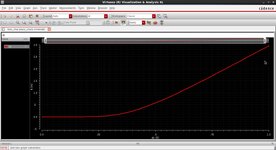
I am trying to plot gm/Id curve of a pmos in 90nm gpdk using Cadence. In it, when I use the ‘gmoverid’ signal directly available in the list, I am getting a max value of 41 (pls see attached snapshot). As I know, it cannot be more than 35 or 36 [as gm/Id = 1/ (n*Vt) = 1/(n*26mV) = 38.5/n and the value of n = 1.3 or 1.4 for bulk Si process].

gm_over_id.jpg


So what am I doing wrong pls?


Thanks and Regards,

Arvind Gupta
 

I would suggest first getting the actual gm and id (or ids) values and calculate the gmoverid to see if it matches with the variable you are getting. I'm not familiar with such PDK, but I would also try and run the same testbench with another PDK (preferably a real one) to check if the funny results are not related to it (gpdk). Its also good to show your testbench/schematics for this simulation
 

Thanks for your reply. I plotted the gm and id curves separately (against sweeping vgs). At 0 v (vgs), the value of gm = 145n and id = 3.5n (snapshots attached). So gm/id = 41.42. This is as per the gm over id graph plotted directly (as per the snapshot in my first post).

gm_at_0_vgs.jpg


id_at_0_vgs.jpg


I am also attaching the test bench snapshot. Basically, I am sweeping the vgs from 0 to 1v for 10um width and 90nm length (pmos) and saving all the dc voltages. Then I am using the results browser to get the expression in the calculator and add it in ADE to plot each of the curves. I am on IC 615. Since Id was coming negative, I added a negative sign to the expression to get the curve in first quadrant.

testbench_pmos.jpg


Do note that the gm/id for nmos is as per the expected behavior (less than 38.5).


Arvind Gupta
 

Attachments

  • id_at_0_vgs.jpg
    id_at_0_vgs.jpg
    283.1 KB · Views: 163

I would not trust the values, since Cadence's GPDK is a fictitious technology with models close to real technology and does have bugs in it and this could be one of the bugs.
 

I would not trust the values, since Cadence's GPDK is a fictitious technology with models close to real technology and does have bugs in it and this could be one of the bugs.

Ok. Then can you pls point me to any PDK (with install instructions) which I can use.

Thanks in advance,
Arvind
 

I would love to recommend Skywater 130 nm which is open source https://github.com/google/skywater-pdk
but there is currently no install instructions for use in Cadence. If you are in a university then maybe ask any professors if they are willing to give you access to a real technology which they use for research. You will have to sign an NDA though.

However, currently you can also use https://eda.ncsu.edu/
This also have install instructions and working with certain cadence versions.

However, I have not personally used them as of now.
Hope it helps :)
 

1. Read about model used by this PDK in Spectre model reference guide.
2. Did you check if your drain current is "pure" drain current (is it equal to source, source-drain, is bulk current negligible)?
3. Did you check how simulator options affecting dc simulation and dcOP computation?
4...
 

I would love to recommend Skywater 130 nm which is open source https://github.com/google/skywater-pdk
but there is currently no install instructions for use in Cadence. If you are in a university then maybe ask any professors if they are willing to give you access to a real technology which they use for research. You will have to sign an NDA though.

However, currently you can also use https://eda.ncsu.edu/
This also have install instructions and working with certain cadence versions.

However, I have not personally used them as of now.
Hope it helps :)
Thanks for your reply. I had tried using NCSU FreePDK and NCSU CDK. However they don’t have spectre model files (.scs files) for simulations. Both of the PDKs have HSPICE compatible model files only. This is strange as at least NCSU CDK (CDK Stands for Cadence Design Kit) should have spectre model files. (I downloaded NCSU CDK ver. 1.6.0 Beta – compatible for IC6.1 and above). I need a pdk for learning purpose. I had written to their help email ID but there is no reply from their side.
--- Updated ---

1. Read about model used by this PDK in Spectre model reference guide.
2. Did you check if your drain current is "pure" drain current (is it equal to source, source-drain, is bulk current negligible)?
3. Did you check how simulator options affecting dc simulation and dcOP computation?
4...
Thanks for your reply.


1.Read about model used by this PDK in Spectre model reference guide.
There is not much spectre model documentation available in with the pdk. Atleast could not find anything relevant to the issue.

2. Did you check if your drain current is "pure" drain current (is it equal to source, source-drain, is bulk current negligible)?
Since I am using the the ‘gmoverid’ function to directly plot this graph, there should not be any error on this case. See the snapshot in my first post.

3. Did you check how simulator options affecting dc simulation and dcOP computation?
No. In the DC simulation setup form, I kept the accuracy settings to ‘moderate’. What other simulation settings do you recommend pls?


Also wanted to ask one thing: While sweeping Vgs, should I sweep the value starting from zero or any other value such as 0.2 etc. If you see the plot in my first post, the gm/Id value is above 41 when Vgs is 0. However, for Vgs at 0.2V, the gm/Id value comes down to 28. (value of gm/Id in case of nMOS is however below 35 for Vgs=0)
 
Last edited:

1.Read about model used by this PDK in Spectre model reference guide.
There is not much spectre model documentation available in with the pdk. Atleast could not find anything relevant to the issue.
Spectre documentation you can find in your spectre installation directory. Inside is a /doc directory consisting of plenty documents.
Spectre model reference guide should be in something like /doc/spmodug subdirectory.

Gpdk90 the most probably is using bsim4 model. Learn about limitations and known issues of this model.

2. Did you check if your drain current is "pure" drain current (is it equal to source, source-drain, is bulk current negligible)?
Since I am using the the ‘gmoverid’ function to directly plot this graph, there should not be any error on this case. See the snapshot in my first post
DC op functions are not part of primitives, nor the direct measurements. You can learn more in "Component Description Language user guide" inside the Virtuoso documentation.
If you want to see your gm/id, perform dc sweep, and calculate all quantities from transistor characteristics (using proper definitions).


3. Did you check how simulator options affecting dc simulation and dcOP computation?
No. In the DC simulation setup form, I kept the accuracy settings to ‘moderate’. What other simulation settings do you recommend pls?
Errpreset is used by transient analysis.
If you don't understand simulator options, keep them default.


Also wanted to ask one thing: While sweeping Vgs, should I sweep the value starting from zero or any other value such as 0.2 etc.
It depends to many things. Usually sweep should be done within operating range (0 to vdd), however results around zero might not be reliable.
 

Hi, let me see if I can replicate the same results on my setup.
Also if you are using just for purposes of learning I would still recommend using NCSU CDK.
it works with cadence as a front end and HSPICE as a simulator in the backend which you have to set from the ADE environment. HSPICE and Spectre might use different numerical ways to compute and simulate circuits but one isn’t right or wrong. So you are good to go.

the following document is from the above page. And it shows how to use HSPICE with Cadence ADE.

So to conclude, don’t wait for me to verify the GPDK is correct use something which does not have any reported bugs as of now. The reason why I am asking you to not use GPDK is because while designing a LNA for our college project 45nm has bug regarding flicker noise not going away even if you keep on increasing transistor width by changing fingers but does reduce when you increase multiplicity . Something, which does not happen in real devices. I am personally tired of cadence’s shizz since I spent a good chunk of time understanding a bug!

hope this helps
Thanks for your reply. Unfortunately, I dont have HSPICE. Also if it is a CDK (Cadence Design Kit), I suppose it should support a Cadence Simulator (Spectre etc).
 

Hi all,

Just checking back if anyone has a solution to my problem. I just need a PDK having Spectre support with near-to-real parameters (the one I have - gpdk90 is far away from a real pdk: gm/Id for pmos is above 41).

Thanks and Regards,
Arvind Gupta.
 

Hi all,

Just checking back if anyone has a solution to my problem. I just need a PDK having Spectre support with near-to-real parameters (the one I have - gpdk90 is far away from a real pdk: gm/Id for pmos is above 41).

Thanks and Regards,
Arvind Gupta.
Try GPDK45nm or GPDK130nm. You might have access to them actually.
 

Try GPDK45nm or GPDK130nm. You might have access to them actually.
Thanks for your reply. I dont have access to these PDKs. If I did, I would not have asked. I just need a PDK with which I can try out gm/Id technique.
 

I think the PDK is fine. You're just looking at extremely low Vgs values and extremely low currents. You are using minimum length and perhaps the model includes some Vds-dependent Ids current source, which would appear as increased gm/Id, indeed.

One thing you could do is to run a transient sim with a tiny sinewave on top of your gate bias, and see how the drain current is modulated. From the ratio of their amplitudes, you would get the 'real' gm/Id.
 

Status
Not open for further replies.

Part and Inventory Search

Welcome to EDABoard.com

Sponsor

Back
Top