Continue to Site

Welcome to EDAboard.com

Welcome to our site! EDAboard.com is an international Electronics Discussion Forum focused on EDA software, circuits, schematics, books, theory, papers, asic, pld, 8051, DSP, Network, RF, Analog Design, PCB, Service Manuals... and a whole lot more! To participate you need to register. Registration is free. Click here to register now.

Gilbert cell mixer

Status
Not open for further replies.

ka7la

Newbie
Joined
Nov 18, 2021
Messages
4
Helped
0
Reputation
0
Reaction score
0
Trophy points
1
Activity points
32
Hello everyone ?

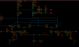
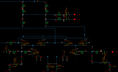
i am designing a mixer for optoelectronic data transmission where the input frequency is 26 GHz, LO frequency 0-13 GHz (or below) and output frequency 26-40 GHz.
First question: the switching quad bjts have to operate in saturation so it should be vb about the same as vc or am i wrong?
Second question: how should i bias the transconductance stage for high conversion gain and low noise?
third question: im using a T-Network as load and to match the output. is it a good idea?
last question: what should be the first step in the design ? the input and ouput matching ?
 

Attachments

  • Gilbert cell.png
    Gilbert cell.png
    53.2 KB · Views: 147
  • Operation point.png
    Operation point.png
    46.8 KB · Views: 135

Quad BJTs work at switch mode and they should be considered as ON-OFF switches so you have to focus on Transconductance stage to obtain Lower Distortion and Optimum Power Gain. Because you will already drive the Quad with almost square wave so "an appropriate biasing of Amplifier Stage" will be followed by Quad Cell. Noise has a second degree priority in Mixer Design, find the optimum bias for Gm part first.
 

Quad BJTs work at switch mode and they should be considered as ON-OFF switches so you have to focus on Transconductance stage to obtain Lower Distortion and Optimum Power Gain. Because you will already drive the Quad with almost square wave so "an appropriate biasing of Amplifier Stage" will be followed by Quad Cell. Noise has a second degree priority in Mixer Design, find the optimum bias for Gm part first.
thank you so much! i have another question please. whate should be the first step in my design ? should i make sure that my input ans output are matched or should i find the optimum bias for Gm part like you said or what?
 

thank you so much! i have another question please. whate should be the first step in my design ? should i make sure that my input ans output are matched or should i find the optimum bias for Gm part like you said or what?
You can start to find optimum bias current for Quad Part by inserting ideal current source instead of Gm driver.
Optimum bias point should give you lower harmonics and sufficient gain.This starting point will redirect you to optimize Gm module.
 

Status
Not open for further replies.

Similar threads

Part and Inventory Search

Welcome to EDABoard.com

Sponsor

Back
Top