bubulescu
Member level 3
Being fairly new to digital filtering I'm trying to make a filter that would have the lowest delay possible while having good filtering characteristics. Call me an idealist, but that is the desired effect.
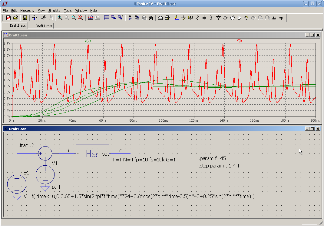
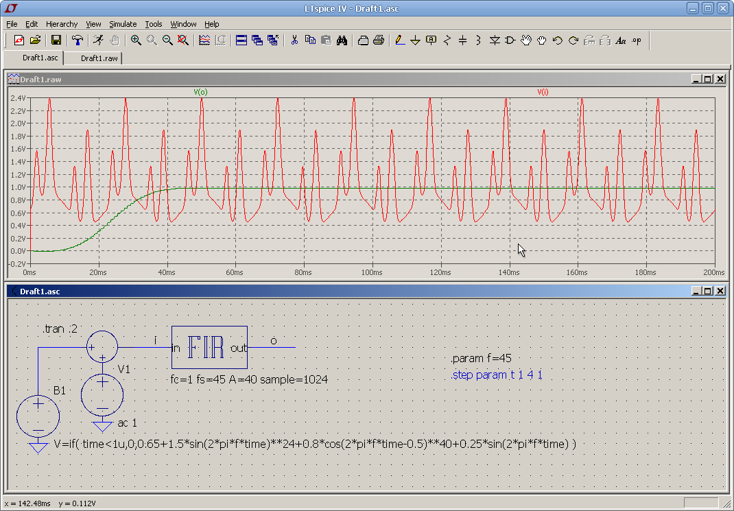
What I want is a response similar to a Bessel filter, that is for the ugly-spikey signal thet's fed to the input, the output should filter it (as) clean (as possible) while fillowing the DC level of it. Now, I understand IIR filters have lower delays compared to high order FIRs while FIRs are better in terms of stability, but I tried analog so far and a high-order Bessel gave the best response, but the delay is... well not satisfactory, so digital filters were suggested and, trying a few free programs found on the internet I realized that IIR behave -- in terms of my needs -- just like their analog counterparts. FIR, on the other hand, if made so that N and sampling were sufficiently low/high, gave better results.
My question: is there a way to achieve the desired effect?
(Read the following only if you think you have time)
So, at this point, I found that Dolph-Chebyshev would be the best suited since it gives the lowest N for the better filtering capabilities, closely followed by Kaiser (not to mention the possibility of calculating with fc/Att in mind from the beginning). But, still, after implementing a FIR in LTspice, the delay could benefit from more improving...
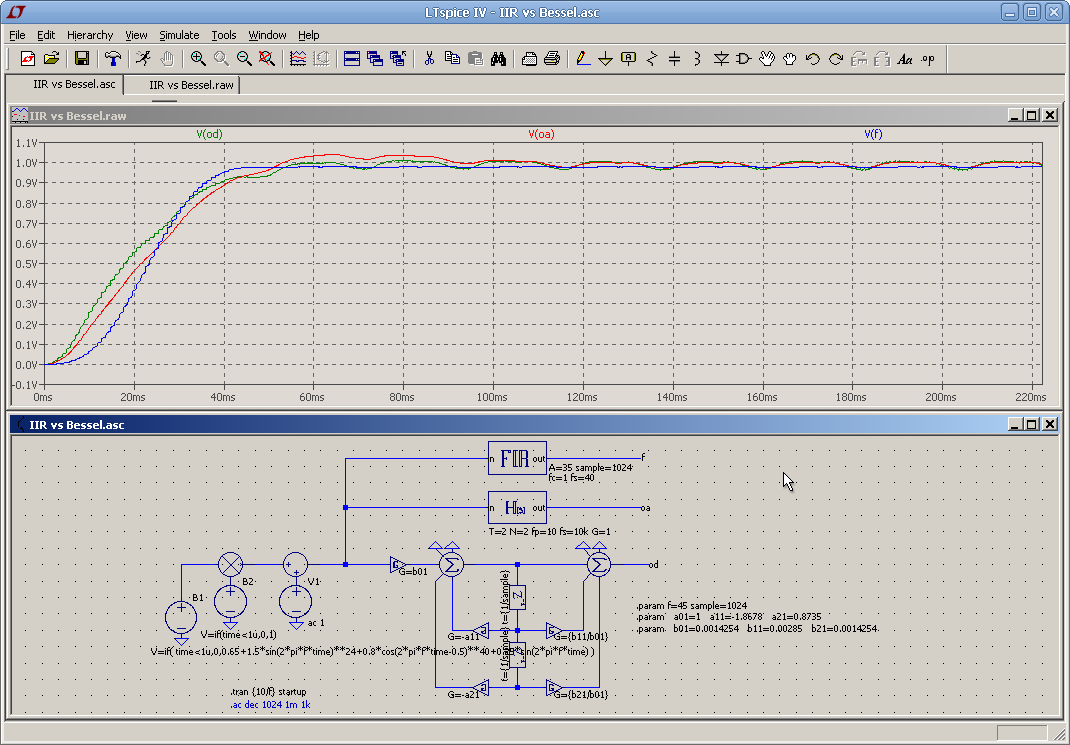
In practise it would serve an active power filter and the input would have twice the frequency of the mains + a DC level, but with a low level mains humm overlapped. So, the FIR I made was done with fc=0.1Hz (I found out it gives a slightly better response compared to 1Hz, while maintaining the large transit bandwidth for minimizing the N), fs=40Hz (the minimum frequency allowed, imposed as a worse case, being 45Hz), sample=1024 and Att=50dB. For the Kaiser window (easier to calculate) I got M=75 and the delay -- calculated from start to 90% of the DC value -- is ~50ms, which would mean 2,5 periods of the standard 50Hz mains, during which time the DC link capacitor would have to sustain everything => a higher value for it. As a comparison, a 3rd order Bessel with fc=10Hz would give very similar results in terms of reaching the 90% DC level, even if the rising time is less steep as with the FIR.
If, however, I would ignore the humm, so that the input would have 2*f_mains as the lowest frequency in the spectre, then I could make the FIR with fs=80, giving a step response of ~22ms, at the cost of a maximum +3% slight overshoot -- acceptable. That would mean just a bit more than a period, ~40% of the initial delay. This result would be something to try to achieve!
In an ideal case of a fixed, non-drifting mains frequency, say 50Hz, then I could have done a simple moving average filter with sampling over half a period, which would have resulted in a steep 10ms response and a "tight-string" DC level at the output. However, real-life forces me to accept the drifts which would distort the results, making it a non-choice. Still, I could consider this a goal to follow and, while I may never achieve it, a result as close as possible is what I would like to get and the reason I mentioned this example was simply for a better viewing of the reasons.
PS: The thought occured to me that a self-adjusting moving average filter could be done, that is measuring the zero-crossing both ways and trying to adapt the sampling period accordingly, resulting in T/2 measure + T/2 adjusting/response = one T delay, but with a poor performance in case of constant/large drifts.
Vlad
What I want is a response similar to a Bessel filter, that is for the ugly-spikey signal thet's fed to the input, the output should filter it (as) clean (as possible) while fillowing the DC level of it. Now, I understand IIR filters have lower delays compared to high order FIRs while FIRs are better in terms of stability, but I tried analog so far and a high-order Bessel gave the best response, but the delay is... well not satisfactory, so digital filters were suggested and, trying a few free programs found on the internet I realized that IIR behave -- in terms of my needs -- just like their analog counterparts. FIR, on the other hand, if made so that N and sampling were sufficiently low/high, gave better results.
My question: is there a way to achieve the desired effect?
(Read the following only if you think you have time)
So, at this point, I found that Dolph-Chebyshev would be the best suited since it gives the lowest N for the better filtering capabilities, closely followed by Kaiser (not to mention the possibility of calculating with fc/Att in mind from the beginning). But, still, after implementing a FIR in LTspice, the delay could benefit from more improving...
In practise it would serve an active power filter and the input would have twice the frequency of the mains + a DC level, but with a low level mains humm overlapped. So, the FIR I made was done with fc=0.1Hz (I found out it gives a slightly better response compared to 1Hz, while maintaining the large transit bandwidth for minimizing the N), fs=40Hz (the minimum frequency allowed, imposed as a worse case, being 45Hz), sample=1024 and Att=50dB. For the Kaiser window (easier to calculate) I got M=75 and the delay -- calculated from start to 90% of the DC value -- is ~50ms, which would mean 2,5 periods of the standard 50Hz mains, during which time the DC link capacitor would have to sustain everything => a higher value for it. As a comparison, a 3rd order Bessel with fc=10Hz would give very similar results in terms of reaching the 90% DC level, even if the rising time is less steep as with the FIR.
If, however, I would ignore the humm, so that the input would have 2*f_mains as the lowest frequency in the spectre, then I could make the FIR with fs=80, giving a step response of ~22ms, at the cost of a maximum +3% slight overshoot -- acceptable. That would mean just a bit more than a period, ~40% of the initial delay. This result would be something to try to achieve!
In an ideal case of a fixed, non-drifting mains frequency, say 50Hz, then I could have done a simple moving average filter with sampling over half a period, which would have resulted in a steep 10ms response and a "tight-string" DC level at the output. However, real-life forces me to accept the drifts which would distort the results, making it a non-choice. Still, I could consider this a goal to follow and, while I may never achieve it, a result as close as possible is what I would like to get and the reason I mentioned this example was simply for a better viewing of the reasons.
PS: The thought occured to me that a self-adjusting moving average filter could be done, that is measuring the zero-crossing both ways and trying to adapt the sampling period accordingly, resulting in T/2 measure + T/2 adjusting/response = one T delay, but with a poor performance in case of constant/large drifts.
Vlad
")