s55
Junior Member level 2
I have an undergraduate level question about RL circuits.
If you visit the following link, there is a simple question about an RL circuit.
 www.bartleby.com
I have a solution of the question, but I don't understand it, and so I would like to ask anybody who knows about it.
The solution says
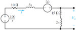
"For t<0, the switch is closed, and the inductors (both L1 and L2) behave like short circuits. The initial current \[I_0\] in the 3H inductor is 100/10=10A."
I pretty much understand this explanation. but the following solution does not make sense to me:
"For t>0, L1 has an initial voltage in s-domain, \[{LI}_{0}=3(10)=30 V\]"
For t<0, L1 becomes a short circuit that means the voltage across L1 is 0V, and the impedance of L1 is also 0 ohm. Then, how does L1 has 30V-s as an initial voltage? Isn't it 0v either?
If you visit the following link, there is a simple question about an RL circuit.
Answered: Figure 13.50 The circuit for Example… | bartleby
Solution for Figure 13.50 The circuit for Example 13.13. 10 N ЗН L1 15 0g t = 0 +. |100 V 2 H3L2 Figure 13.50 Full Alternative Text
www.bartleby.com
I have a solution of the question, but I don't understand it, and so I would like to ask anybody who knows about it.
The solution says
"For t<0, the switch is closed, and the inductors (both L1 and L2) behave like short circuits. The initial current \[I_0\] in the 3H inductor is 100/10=10A."
I pretty much understand this explanation. but the following solution does not make sense to me:
"For t>0, L1 has an initial voltage in s-domain, \[{LI}_{0}=3(10)=30 V\]"
For t<0, L1 becomes a short circuit that means the voltage across L1 is 0V, and the impedance of L1 is also 0 ohm. Then, how does L1 has 30V-s as an initial voltage? Isn't it 0v either?