Continue to Site

Welcome to EDAboard.com

Welcome to our site! EDAboard.com is an international Electronics Discussion Forum focused on EDA software, circuits, schematics, books, theory, papers, asic, pld, 8051, DSP, Network, RF, Analog Design, PCB, Service Manuals... and a whole lot more! To participate you need to register. Registration is free. Click here to register now.

[SOLVED] fan 3rd wire, BY IC WITH THIRD WIRE ALARM (LOCKED ROTOR)

Status
Not open for further replies.

mehdok

Newbie level 4
Newbie level 4
Joined
Mar 9, 2013
Messages
5
Helped
0
Reputation
0
Reaction score
0
Trophy points
1,281
Activity points
1,320
hi
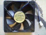
i have bought a new 12cm, 12V fan for pc, it has 3 wire, so as usual i thought the 3rd wire is for showing fan speed, but it didn't work that way.
i searched fan model and i found "model number scheme" for all of company's fans, as u can see in the below image, this fan has the following :
function description : By IC with alarm(IRD) (the fan model have number 2 in that position)
i think this is the function of 3rd wire, so what this mean and how i can use this ?
tnx
pic_model.jpgSPM_A0009.jpgSPM_A0008.jpgSPM_A0007.jpg


you can also see the function here


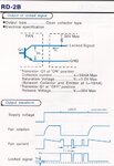
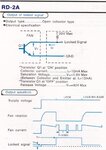
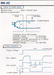
i also have found this schemes for function of 3rd wire, but i have a little knowledge of electronic, so can you describe this function to me with simple words ?
rd-2c.jpgrd-2b.jpgrd-2a.jpg
 

These fans have an open collector transistor pulse output that has a frequency related to the fan speed. Usually your micro watches the pulse output and uses the output frequency to determine fan condition/fault and speed.
 

These fans have an open collector transistor pulse output that has a frequency related to the fan speed. Usually your micro watches the pulse output and uses the output frequency to determine fan condition/fault and speed.
most of 3 wire fan do this, and u can use the 3rd wire for monitoring speed, but this fan not doing this. can u explain what is the Locked Signal in that image ?
is it output or input ?
 
Last edited:

The datasheet specifies the lock monitor as an open collector output, along with an vizual description of it's operation. What are you missing?
 

The datasheet specifies the lock monitor as an open collector output, along with an vizual description of it's operation. What are you missing?
as i said i have no knowledge of electronic, so can u explain to me what is the main function of this 3rd wire, and how i can use it?
 

as i said i have no knowledge of electronic, so can u explain to me what is the main function of this 3rd wire, and how i can use it?
I already did.
 

I already did.
tnx, but you said it's related to fan speed and i said it's not a fan speed sensor(according to model scheme image). please, again take a look at that image and model in my fan.

- - - Updated - - -

I already did.
tnx, but you said it's related to fan speed and i said it's not a fan speed sensor(according to model scheme image). please, again take a look at that image and model in my fan.
 

The supply voltage shows the supply of the fan
The fan rotation shows the fan speed
The fan current shown the current of the motor
The locked signal graph shows the output of the third open collector pin when a pullup resistor is used as shown in the schematic.

The power supply graph has a section named lock, as you can see by the fan rotation graph in this area the fan is stopped so you get an alarm signal at the locked pin.
In the lock release section of the supply graph you see that the rotation speed increases again and the lock signal (alarm) goes high again

What I describe is for 2C, each of the three pictures shows different behaviour , one goes low on alarm, one goes high on alarm etc
 
  • Like
Reactions: mehdok

    mehdok

    Points: 2
    Helpful Answer Positive Rating
My interpretation is that the lock is an input caused by say holding the fan in a locked (stationary) position, then the lock signal either shows high, low or a series of pulses, I would assume the pulses are a response to the fan current pulses as the fan attempts to move the fan against the lock. So yes I'm sorry my original post was a generalisation based on fans I have previously used not your specific fan datasheet.
 

The supply voltage shows the supply of the fan
The fan rotation shows the fan speed
The fan current shown the current of the motor
The locked signal graph shows the output of the third open collector pin when a pullup resistor is used as shown in the schematic.

The power supply graph has a section named lock, as you can see by the fan rotation graph in this area the fan is stopped so you get an alarm signal at the locked pin.
In the lock release section of the supply graph you see that the rotation speed increases again and the lock signal (alarm) goes high again

What I describe is for 2C, each of the three pictures shows different behaviour , one goes low on alarm, one goes high on alarm etc

tnx so,
1) what/where is pullup resistor?
2) what is the usage of this locked signal? is it just saing that fan is working or not?
3) in the image you described the supply voltage is constant, so what makes fan going in lock state?

- - - Updated - - -

My interpretation is that the lock is an input caused by say holding the fan in a locked (stationary) position, then the lock signal either shows high, low or a series of pulses, I would assume the pulses are a response to the fan current pulses as the fan attempts to move the fan against the lock. So yes I'm sorry my original post was a generalisation based on fans I have previously used not your specific fan datasheet.

tnx, but i can't imagine any usage for this behavior, can you?
 

what/where is pullup resistor?

The output of the third pin is what we call an open collector, what that means is that the transistor can either be on in which case it grounds the output or it is off in which case the output is floating.
A floating pin is not very useful because the state is undefined (it is a high impedance mode) so that is why the pullup resistor is used, it is a resistor from the third pin (which is the transistor collector) to the positive power supply and forces a high state when the pin is floating.

what is the usage of this locked signal? is it just saing that fan is working or not?
It is just an alarm pin intended to inform you when the fan has stopped rotating so you can take further action

in the image you described the supply voltage is constant, so what makes fan going in lock state?
Some kind or object that may stop the fan or maybe even a multifunction
 
  • Like
Reactions: mehdok

    mehdok

    Points: 2
    Helpful Answer Positive Rating
Status
Not open for further replies.

Part and Inventory Search

Welcome to EDABoard.com

Sponsor

Back
Top