Continue to Site

Welcome to EDAboard.com

Welcome to our site! EDAboard.com is an international Electronics Discussion Forum focused on EDA software, circuits, schematics, books, theory, papers, asic, pld, 8051, DSP, Network, RF, Analog Design, PCB, Service Manuals... and a whole lot more! To participate you need to register. Registration is free. Click here to register now.

External input vs Battery switch SPDT >=6A

Status
Not open for further replies.

destmaster84

Newbie
Joined
Apr 22, 2022
Messages
4
Helped
0
Reputation
0
Reaction score
0
Trophy points
1
Activity points
25
Hello,
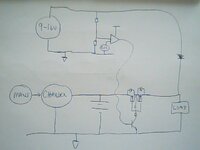
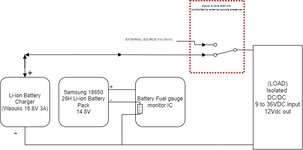
I have a system powered form a 14.8V (nominal) battery; It's a LiOn and can be recharged by an appropriate battery charger with a 16.2V output. I want to have an external power source (DC 9V to 36V) that, when plugged in, power my system and also disconnect the battery (and obviously the charger). Upon external power disconnection the system must return to the battery source. The system load is around 6A, but I would to like to support up to 10A. Someone can suggest a nice MOSFET based circuit avoiding use of mechanical relays.
 

Hi,

so we have some parts:
* battery
* charger
* load (what nominal working voltage?)
* external power source

Draw a sketch on how they are connected and how they can be controlled (charger).
Also show us your idea where you want to place the switches,
No need to be perfect, just your idea.

Also tell us:
The battery has varying voltage...and the input has a wide voltage range....how does your load handle this?

Klaus
 

Hi, there is the attached, if its any use?
 

Attachments

  • Charger_supply changeover.jpg
    Charger_supply changeover.jpg
    57.9 KB · Views: 86

Hi,

so we have some parts:
* battery
* charger
* load (what nominal working voltage?)
* external power source

Draw a sketch on how they are connected and how they can be controlled (charger).
Also show us your idea where you want to place the switches,
No need to be perfect, just your idea.

Also tell us:
The battery has varying voltage...and the input has a wide voltage range....how does your load handle this?

Klaus
Hi, attached the sketch... I hope that is all clear
I need also to protect the pluggable elements (battery, external source and battery charger) from accidental reverse polarity.
 

Attachments

  • supp_diagram.jpg
    supp_diagram.jpg
    28.5 KB · Views: 83

Hi,

not clear how the battery is involved in your circuit. I miss a connection to it´s "+" somehow.

Basically @cupoftea ´s approach is O.K.

If this is my job:
* I´d use a dedicated power supply switches, designed exactly for this
* I´d avoid using a discrete diode because of it´s power dissipatioin at 10A. Consider to use an "ideal diode" circuit.

Klaus
Sorry, I missed it.
Correct version attached.
Thanks @cupoftea for your suggestion

supp_diagram.jpg
 

The problem with the ideal diode by itself is that it will not connect the external source if it is less than the battery voltage.
You will need some additional circuitry.
I'm seeing if I can come up with something that will work.
 
Last edited:

Hi,

You talk about two ideal diodes, I just talked to replace the discrete diode in cupoftea's circuit with an ideal diode.

Klaus
 

Status
Not open for further replies.

Similar threads

Part and Inventory Search

Welcome to EDABoard.com

Sponsor

Back
Top