Continue to Site

Welcome to EDAboard.com

Welcome to our site! EDAboard.com is an international Electronics Discussion Forum focused on EDA software, circuits, schematics, books, theory, papers, asic, pld, 8051, DSP, Network, RF, Analog Design, PCB, Service Manuals... and a whole lot more! To participate you need to register. Registration is free. Click here to register now.

EMC test causes input filter instability

cupoftea

Advanced Member level 5
Joined
Jun 13, 2021
Messages
2,682
Helped
54
Reputation
108
Reaction score
116
Trophy points
63
Activity points
14,099
Hi,
We had a mobile EMC test guy come to us to do conducted EMC and conducted immunity and susceptibility on our 24Vin to 12Vout 20W SMPS LED driver
for handrail useage in railway stations.

He put a 500uH inductor in the supply to the LED driver, which obviously totally messed up the LED driver as it went into input filter
instability. We'd have had to use an enormous input capacitor to work with such a big inductor. He said the need of the 500uH inductor
was to protect his RF amplifier during the conducted immunity tests. I thought they just needed an RF attenuator for that?

Also, its the case that most LISNs for this type of DCDC are actually putting a 5uH or 50uH inductor in the supply to the LED driver. Even this means
having to design the input filter with more capacitance than would otherwise be needed.


Why don't all the App Notes of these high switching frequency DCDC controllers tell about the fact that you wont be able to use a tiny MLCC
capacitor bank after all?...because it wont work with the LISN inductor.

I mean, in the application, our device will work on the output of a Meanwell or other Power Supply which has a very large output capacitor,
and causes no problems for our tiny MLCC input capacitor bank.....but due to the EMC testing, we have to re-design it to be able to work with the
LISN's output inductor

Is this not a failure of the EMC testing procedure?
 
500uH - on both P and N would be there to reduce noise from the mains upsetting the test.

50uH and large caps to earth on the mains side of these L's ( earth current hazard - be aware ) is the more usual approach - sometimes with 250uH upstream for the mains filtering reason, ( often called a 50/250uH V LISN )

I can see how 500uH would resonate with small mains caps on your power supply if the controller is not well damped - and indeed - 500uH is an odd choice considering the 50/250uH V LISN is the highest L I know of - and there are substantial caps to earth between the two - that effectively remove the 250uH effect.

Get your own LISN ( 50uH ) and then seek a re-test with a 20dB pad to the spec ann.
--- Updated ---

note page 16 well of that document.
 
500uH - on both P and N would be there to reduce noise from the mains upsetting the test.
Thanks, sorry, this was a EMC test of a DCDC SMPS. Just 24Vin.

Yes as you kindly say, 5uH (auto) or 50uH (industrial) seems the more common value for a LISN.....what gets me is that there's only 100nF downstream of it. So basically it means any input filter has to be designed for that.....so the input filter will be (much) bigger then need be...and (much) more costly.

I cant understand why App Notes for high frequency DCDC switchers make no mention of this?....i mean, most of them even go to the extent of explaining Ohms law measurements.........which surely an engiener would know anyway....and then they fail to explain stuff that could wreck the entire project...because clearly, if you are making a low power dcdc smps, then having to have a 50uH inductor placed in its supply line is going to ruin its behaviour beyond belief unless you have well overdamped the input filter) .......and really, when you are installing into places where you know you wont have to have such 50uH lines....then you are literally having to design in loads of extra cost just to handle connection to the EMC equipment.

This sounds like madness.

Whats the point of the GaN revolution, where super high frequency SMPS means tiny MLCC input cap banks are ok.....but then it cant be connected to an EMC tester....unless you make the input filter so big that you might as well have used a lower switching frequency and just chucked the GaN FETs away.
The semiconductor marketeers are mugging people over.

The 5uH inductor in a LISN box will also never look like so many metres of power cable...because in the power cable, the cable inductance is intermingled with the cable capacitance, (and resistance) and so it doesnt actually look like a 5uH inductor....the cable length is a transmission line with distributed L and C.

And how do they decide what length of cable the LISN is supposed to look like?.....you might know that the cable length in your application is always going to be well below what the LISN has been set up to look like.
 
Last edited:
Hi,
Page 2 of this...
https://www.tekbox.com/product/TBL0550-1_Manual.pdf

..shows a 5uH LISN with a 5uH inductance.

But 07:25 of this video, shows the 5uH LISN schematic with some 470R resistors connected across the inductance..

Do you know which one is used by the standards bodys?

Also, what is the output filter of the power supply used at the EMC labs, upstream of the LISN? (pse see attached).....its output CLC filter affects the peak of the ring-up voltage when the DUT is suddenly switched ON....there is a danger of overvoltaging something at the DUT. (as in LTspice and PNG attached)
 

Attachments

  • LISN setup.png
    LISN setup.png
    48.7 KB · Views: 18
  • LISN set up.zip
    1.2 KB · Views: 19
P & N = pos & neg.
--- Updated ---

A DC/DC converter with a soft start - and a with a load that is only gradually varied can handle 500uH on the input side if the control is suitably damped

else you will have to specify in the data sheet that 2200uF ( or what-ever ) external is to be placed across + ( Pos ) & - ( Neg ) to partially negate the increased series L feed - for EMC test.

As there is no EMC test I am aware of that requires 500uH - you are really chasing fairies . . . ,

also - super high freq converters can have slow damped control loops if required

any converter designed to operate dynamically very quickly would of course need a low Z supply to do so - even if this were supplied by the user - e.g. several 4700uF caps on the front end.

As we see - your plight is non sequitur - you either have an application requiring fast response ( where the 500uH test is ridiculous ) or you don't.
 
Last edited:
Some considerations in this thread (e.g. how many meters of cables a LISN shall represent) are probably interesting topics for an EMC lecture or text book, they are leading to nothing in the context of this thread.

Test setups are specified in applicable EMC standards. The basic question is: according to which standard is your product tested, is the test performed appropriately by the lab?

You are stating in the first post that your product has problems to operate with standard 5 uH low voltage DC LISN. If the product is designed for general usage, it should surely be able to deal with some amount of source inductance. Otherwise, some standard EMC tests can be possibly not performed, the restricted usage must be stated in the conformance declaration.
--- Updated ---

As there is no EMC test I am aware of that requires 500uH - you are really chasing fairies . . .
I'm neither aware of a similar specification. Some surge and burst tests however use larger decoupling inductors than 5/50 uH, we should know which standard is applied.
 
Last edited:
I'm a big fan of "test it like you use it" and this ain't that.

More like, "test it like somebody real stupid with an
awfully long roll of wire might possibly use it someday".

But I think that, knowing this sensitivity, your application
notes (if any) and spec ought to declare an upper bound
to source inductance and/or guidance about killing it
with proper C (and ESR). Would then the EMC lab be
required to adhere to published application bounds?
 
Some surge and burst tests however use larger decoupling inductors than 5/50 uH
Thanks, i dont suppose you could tell which standard please at all? ie , which standard has the biggest connected inductor, and how big it is?....also, the #4 above shows the true schem of a 5uH LISN...do you have the true schem of a 50uH LISN?
Also. the series resistance of the 50uH inductor in the 50uH LISN. (I think its 0.04 Ohm max?).
The 5uH one is 0.25 Ohms max.?
 
The standards show how to make a 50uH LISN inductor ( and the 250uH filtering one too ) there is no lower bound on the DC resistance - but the L must be damped according to the spec ( damping resistor every few turns ).
 
Thanks, any chance anyone can give the name of the standard?, so i can get the schem of the 50uH LISN, then i can pay for 24hrs of access, which i believe is legal

 
1716455294693.png

--- Updated ---

1716455449317.png

--- Updated ---


--- Updated ---

1716456024550.png

--- Updated ---

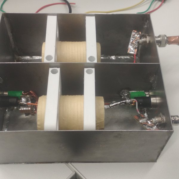
1716456091862.jpeg

--- Updated ---

1716456252463.png


from: -


worth a read
--- Updated ---

CISPR16 has all the details from memory
--- Updated ---

1716456994517.png

--- Updated ---

1716457067237.png

--- Updated ---

 
Last edited:

LaTeX Commands Quick-Menu:

Similar threads

Part and Inventory Search

Welcome to EDABoard.com

Sponsor

Back
Top