Continue to Site

Welcome to EDAboard.com

Welcome to our site! EDAboard.com is an international Electronics Discussion Forum focused on EDA software, circuits, schematics, books, theory, papers, asic, pld, 8051, DSP, Network, RF, Analog Design, PCB, Service Manuals... and a whole lot more! To participate you need to register. Registration is free. Click here to register now.

efr32fg14 EVM harware difference between Input and pushpull

Status
Not open for further replies.

yefj

Advanced Member level 4
Joined
Sep 12, 2019
Messages
1,192
Helped
1
Reputation
2
Reaction score
3
Trophy points
38
Activity points
7,199
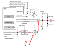
Hello, in the code bellow i see that gpio pin is defined as input or as pushpull.
I am trying to look at the manual diagram shown bellow , how "hardware wise" pushpull work and how "input" works?
Thanks.
data sheet:

reference manual page 1069:
1672955217683.png

Code:
GPIO_PinModeSet(BSP_GPIO_PB0_PORT, BSP_GPIO_PB0_PIN, gpioModeInput, 0);
//  GPIO_PinModeSet(BSP_GPIO_PB1_PORT, BSP_GPIO_PB1_PIN, gpioModeInput, 0);

  // Configure LED0 and LED1 as output
  GPIO_PinModeSet(BSP_GPIO_LED0_PORT, BSP_GPIO_LED0_PIN, gpioModePushPull, 0);

  GPIO_PinModeSet(BSP_GPIO_LED1_PORT, BSP_GPIO_LED1_PIN, gpioModePushPull, 0);
 

Not sure what you are asking, the function seems pretty obvious and is similar to most modern uC GPIO. Think of the output with enable as a 74HC125 tri-state driver. In input mode the driver is permanently disabled.
 

Hello FVM, i have a button connected to the Input,i have found a diagram from other website shown bellow.
when i press the button connected to gnd i see how it works.
but when the button is not prssed and we have open circuit how does the Input functions?
Thanks.

1672993673341.png
 

If you connect a button (lets assume single-throw switch to ground) to the input, you need a pull-up resistor. Either place external pull-up or activate internal pull-up of the pin.
 

Hello,i have attached the scematics and assembly prints of similar board .
as we can see one side of the button connected to ground.
the other side of the switch connected to mcu PD5,how can i want what happence in the mcu shown in the diagram bellow

What is the component marked red ? it looks like a buffer with hysteresis in it.
in gpio we have high or low results to store
What is DIN DOUT?
1673009582778.png

1673008522295.png

1673008997062.png

1673009161450.png
 

Attachments

  • BRD2102A-A04-schematic.pdf
    997.6 KB · Views: 108
  • PCB2102A-A02-assy-draw.pdf
    2.3 MB · Views: 105
  • 1673009522444.png
    1673009522444.png
    101 KB · Views: 89

Status
Not open for further replies.

Part and Inventory Search

Welcome to EDABoard.com

Sponsor

Back
Top