Continue to Site

Welcome to EDAboard.com

Welcome to our site! EDAboard.com is an international Electronics Discussion Forum focused on EDA software, circuits, schematics, books, theory, papers, asic, pld, 8051, DSP, Network, RF, Analog Design, PCB, Service Manuals... and a whole lot more! To participate you need to register. Registration is free. Click here to register now.

ECG circuit design with AD620

Status
Not open for further replies.

turko2489

Newbie level 4
Joined
Jan 19, 2013
Messages
7
Helped
2
Reputation
4
Reaction score
2
Trophy points
1,283
Activity points
1,322
u can use this circuit diagram.. i get nearly original ecg signal. **broken link removed**
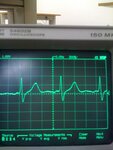
figure shows my ecg signal..
also i share circuit diagram that i used.. circuit diagram of ECG.jpg
(the last part of circuit is T twin 50hz noise filter)
 

Attachments

  • IMG_0488.JPG
    IMG_0488.JPG
    658 KB · Views: 343
Last edited:
I did build the circuit but I could not get an output. Could you give us a feedback
 

i m sorry this reply is too late but i got that output.. if u still want help i can do something
 
  • Like
Reactions: RAFIUL

    RAFIUL

    Points: 2
    Helpful Answer Positive Rating
Have u got the output. Please help me for the same. I have reffered circuit from AD620 datasheet but i am not able to get the output.
 

i didnt understand what kind of help do you need? u built this circuit and u can not obtain this output?? or you mention something else?
 

i didnt understand what kind of help do you need? u built this circuit and u can not obtain this output?? or you mention something else?

I designed notch filter using LM358, but it not quite right. Did you analyze di freq response? Did it really worked? Would you please share the prospice output?

Thanks.
Ali,
 

Why don't you feed the 0V with inverted common mode interference to the patient's leg as shown on the datasheet?
 

Also, What output with input shorted to Gnd or with 1M to Gnd.

Did you check DC levels on every pin for proper bias?

Did you use shielded coax or twisted pair?

Also many items are inverted to conventional wisdom.

Positive V should be on top, not bottom, and Ground pointing down, not up.
 

Hi,
I am triying to built similar ECG circuit. But i stuck at iisolation side. Can you please help with that. Can you advise an example referance design of an ECG circuit for me.

Thank you.
Best Regards.

Also, What output with input shorted to Gnd or with 1M to Gnd.

Did you check DC levels on every pin for proper bias?

Did you use shielded coax or twisted pair?

Also many items are inverted to conventional wisdom.

Positive V should be on top, not bottom, and Ground pointing down, not up.
 

Status
Not open for further replies.

Similar threads

Part and Inventory Search

Welcome to EDABoard.com

Sponsor

Back
Top